1 vs 2 Sided Facet Density Calculation Error for Transparent Facets?

I was working on simulation a vacuum gauge on a side port and was seeing some issues with values of densities at the entrance to the gauge vs density in the gauge sensor volume. So I did a simpler geometry and I’m seeing a difference for how Molflow is calculating the density of 1 vs 2 sided transparent facets. So I created a simplified test model to figure the problem out. Below is a simple box with SF=1 for non-transparent surfaces to see the effects of the direction of the single pass particle flux.

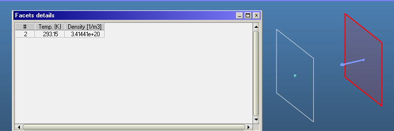
The source is 1-sided and it seems to be counting the desorption particles correctly toward its density. 0.001 cm after the source facet is a 1-sided transparent facet facing the source that should have the same particles going past it, but its calculating 2x the density. However, if you set its SF=1 and Opacity=1 then you get the same density as the source, see below. If you flip this facet so it’s pointing away from the source you get zero density as expected. 0.001 cm after that facet is a 2-sided transparent facet facing the source that should have the same particles going past it too and it has the same density as the source. But is it just getting it correct because it is averaging a value that is 2x higher with zero from the other side. I’m assume you are averaging for density??? For 2-sided transparent facets it is wrong to take the average, you have to count particles from both directions towards its density. Same for pressure too, but it tricker because it can have a net direction too, as oppose to density which is scaler. Same issue with impingement rate…maybe it makes sense to average or take a net value. This is why I hate using 2-sided surfaces because you have to really understand what Molflow is doing under the hood and what your particles should be doing or you will interpret the results wrong. Attached is the Molflow file. Using version 2.9.24 on a M1 Mac Pro

Best,
Alan

Beam Speed Distribution Test.zip (224.4 KB)

Hello Alan,

As you remember from our discussion ~10 years ago during my Phd, Molflow is an event-driven simulator only aware of physics on the walls. It has no test cubes or other volume-aware features (even though we plan to add for custom parameters for the background scattering).

Instead of saying “it’s impossible to measure density”, I made a best-effort approach to estimate the density, that works most - but not all - of the time.

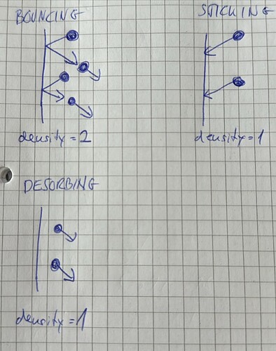
Look at the three cases above. It’s obvious that when sticking=1 or desorption is 100%, the density is half of the bouncing case. The problem is, Molflow can only detect incident hits on the wall, so in all three cases it would measure the same density!

Therefore, I added a correction factor, I paste the code below, it’s enough if you read my comments:

/**
* \brief Function that calculates a density correction factor [0..1] (with 1.0 = no correction)
* \return correction factor value [0..1]
*/
double InterfaceFacet::DensityCorrection() {
	//Correction for double-density effect (measuring density on desorbing/absorbing facets):

	//Normally a facet only sees half of the particles (those moving towards it). So it multiplies the "seen" density by two.
	//However, in case of desorption or sticking, the real density is not twice the "seen" density, but a bit less, therefore this reduction factor
	//If only desorption, or only absorption, the correction factor is 0.5, if no des/abs, it's 1.0, and in between, see below

	if (facetHitCache.nbMCHit > 0 || facetHitCache.nbDesorbed > 0) {
		if (facetHitCache.nbAbsEquiv > 0.0 || facetHitCache.nbDesorbed > 0) {//otherwise save calculation time
			return 1.0 - (facetHitCache.nbAbsEquiv + (double)facetHitCache.nbDesorbed) / (facetHitCache.nbHitEquiv + (double)facetHitCache.nbDesorbed) / 2.0;
		}
		else return 1.0;
	}
	else return 1.0;
}

This works in practically all the cases, except when you “fool” Molflow, or in other words, you make it impossible to deduce the real density. Let’s walk through your geometry:

  • Your desorbing facet, leftmost in your screenshot, counts only desorptions. Therefore Molflow uses a correction factor of 0.5 because it knows that particles are not coming in, only going out.
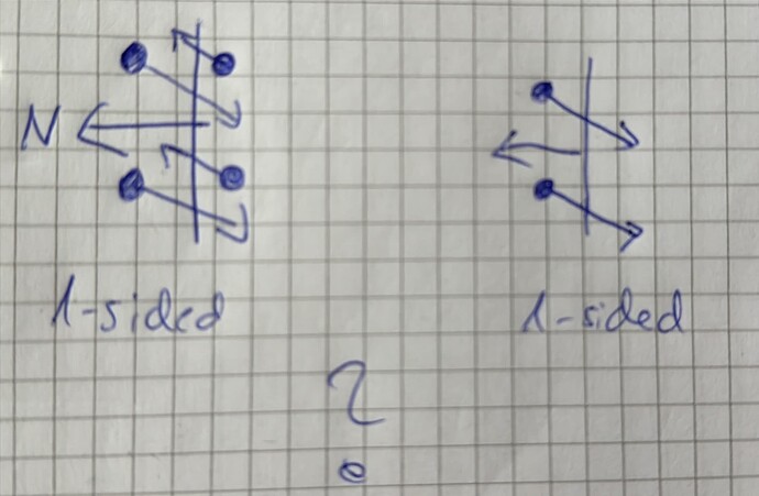
  • Your next facet, looking left, transparent, cannot apply a correction factor because it doesn’t know what’s going on behind it. Look at the two cases, it cannot decide which is going on, so it assumes that particles are coming from its back, it just can’t detect them:

(you and me, of course, know that it’s the right-side case, but most MolFlow geometries are isotropic, so the left, general case is the safer assumption)

Therefore it overestimates the density by a factor of 2. When you switch to 2-sided, it correctly detects that there are no particles coming from the back, and shows the correct density (half of the 1-sided version)

  • Your last facet, pointing away from the source can’t detect any hit so it - incorrectly - shows 0 density.

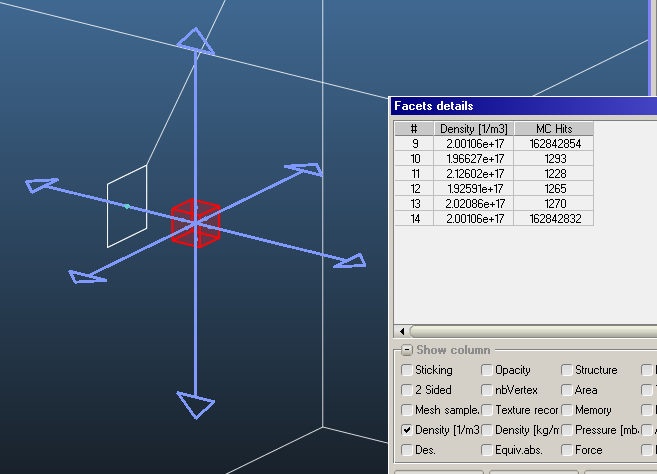
Just to be clear, as you know as well, density is a scalar, it shouldn’t be affected by the facet’s orientation. As you can see, even in your jet geometry, Molflow calculates the density well, despite very different number of hits, regardless of orientation, if you “help” it by giving information from both sides:
image

(These are transparent two-sided facets. 9 and 14 are perpendicular to the jets, 10-13 are parallel).

But please understand that 1-sided facets are usually located as the wall of the geometry, and it would be unacceptable to average the 0-density on the outer side of the geometry and the actual density, nor would it be acceptable to double the estimated density in the volume just because the facet is 1-sided.

Conclusion:

  • I can’t measure the density directly, so I implemented a best-effort estimation
  • Even in non-isotropic systems, this shows correct density, but transparent facets need to be 2-sided
  • 1-sided transparent facets in a non-isotropic system are an edge case where I believe there’s not enough information to correctly show the density, only to assume isotropy, which in your case overestimated the density

Final note:

  • 2-sided facets aren’t that mythical - they simply detect hits from both sides, and in any formula where there is normalization by facet area, they double the facet area (pressure, impingement, density). Apart from double-counting the area, I don’t do further magic or corrections on them.
I was trying to find our old discussion in the forum from long ago, but didn’t have any luck. So I posted this. So if I understand correctly you automatically double the density for any desorption, adsorption and hit event. Then you correct for the double counting of desorbing/adsorbing particles. While for reflected particles you automatically are making the reflected particles to be specular and have the same energy as the incident which may go against the settings for that facet. In the case of 1-sided transparent facets you don’t correct because they are neither adsorbing/desorbing or reflecting…correct? If you are going to hack the other cases you should also take this into account if it’s transparent and correct for it too.

You should be able to properly implement the density measurement without having to hack a correction factor so it will be correct all the time and properly match the settings for that facet. Of course molflow does more than detect incident hits…you are already doing this for desorbing particles which are outgoing not incident. For reflecting particles, once it determines it’s going to bounce the particle it must calculate a new reflection angle and velocity all based on the setting for that facet. At which point you can also calculate the 1/Vperp value for the reflected particle and add it to the density counter for that facet rather than assume its the same as the incident particles.

This is the proper way to do it and will always give the correct answer for all cases. For me 1-side facets are not outliers, I use 1-sided transparent facets all the time to determine directional flux flows. Also most of my walls are pumping and/or cold so reflected particles are very different from the incident which your hack will incorrectly calculate the densities.

As for double sided not sure how your hack works. Are you also double counting? You can also properly implement the density for doubled sided as well…though it’s a bit more complicated in how you combine the two side into one textured results since they really are two back-to-back 1-sided surfaces, but molflow simplifies it as a single facet. I really only use 2-sided for semi-transparent surfaces (wire meshes, grated holes, etc…) since to do this as 3D 1-sided facets is just a pain in the ass and is time consuming. The only other case is for transparent analysis planes. Any thing else I wouldn’t trust the results unless you really understand your correction hack and the limitations it has.

So to summarize for the transparent analysis facets…

  1. I can divide by 2x the results from the 1-sided density. What about the pressure? Also divide by 2x? I think the impingement rate is ok???

  2. 2-sided gives the correct density. What about pressure and impingement rate? Is it an average, sum or net value from the two sides.

Best,
Alan

Hello Alan,

Thank you for the detailed notes, but I believe your reasoning has a flaw.

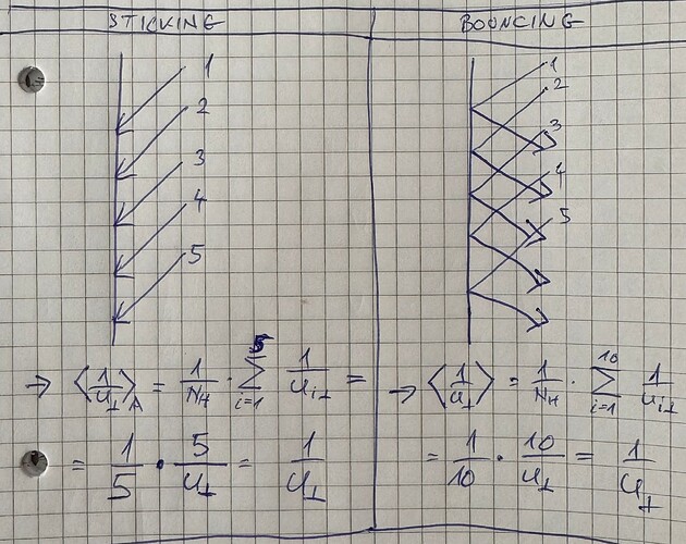
Taking your 5-particle example, look at the two cases below:

  • In the first case, you count 5 v_ort components and normalize by 5.

  • In the second case, you count 2*5=10 v_ort components and normalize by 10.

As you can see, your calculation gives the same density for both cases, whereas the physical solution is twice the density in the bouncing case vs. the sticking case.

I think you have double-count the orthogonal components in case of bounces, but only normalize by the number of incident hits. Doing that corrects the results, but we’re back to the original problem in case of 1-sided transparent facets.

(By the way, Molflow - as you suggest - already calculates the incoming and outgoing perpendicular velocities in case of bounces, and adds them to the counter separately. The question is only what to normalize this “sum of perpendicular speeds” counter with)

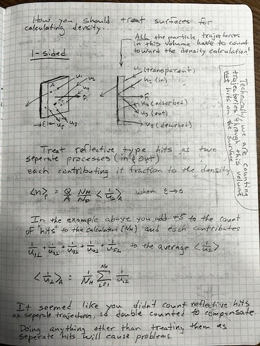
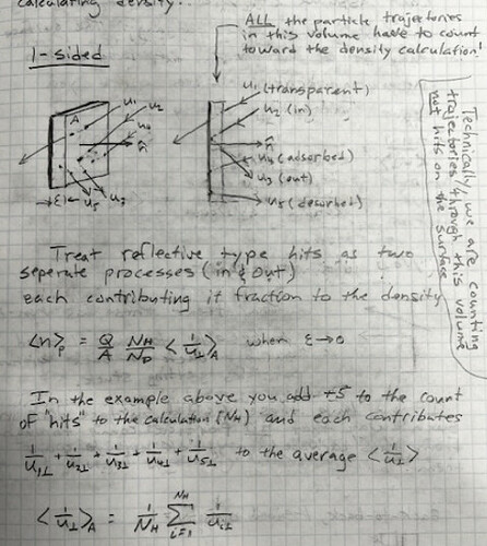
Yes, the average <1/Vperp> is the same in both cases, but not the density, which gets multiplied by the same Nhits used to calc <1/Vperp>. So you get 2x the density as it should be for the bouncing case since it has twice the “hits”. I think it is better not to use the term Nhit, but rather Npass so as not to confuse the number of hits on the surface with the number of passes through this infinitely thin sheet volume.

Avg Density = Q/A x Npass/Ndes x <1/Vperp>

where,

<1/Vperp>=1/Npass x sum(1/Vperp)

or let the Npass terms cancel each other and just use

Avg Density = Q/A x1/Ndes x sum(1/Vperp)

in which case the sum(1/Vperp) will be twice as large for the bouncing case. In general, this sum should include all types of passes: adsorbing, desorbing, reflected…which is just the same as a combination of the first two).

For this simple example we are assuming the incoming and outgoing Vperp are the same. In many of my simulations they are not, which is why one needs to calc 1/Vperp for all the incoming and outgoing particles seperately and use the above formula rather than your double counting with correction scheme to accurately calculate the density. Since you are already keeping track of 1/Vperp for all the incoming and outgoing particles it should be straight forward to implement the correct formula for calculating the density.

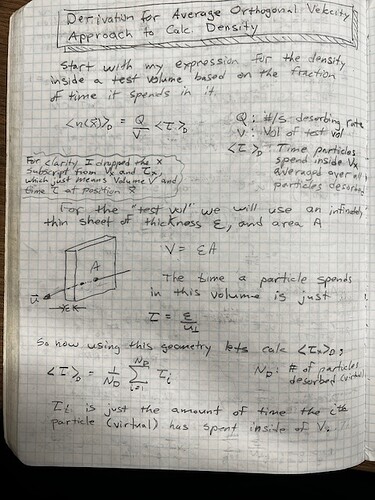
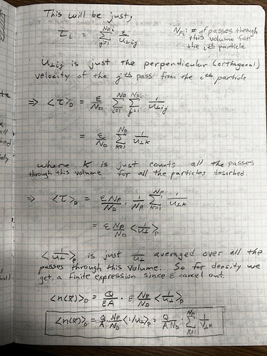
I’ve updated my density derivation that I sent you long ago to make it less confusing between hits and passes.

I wanted to comment a bit more on the use of 1-sided and 2-sided facets. My general philosophy on this is…

Real Surfaces (1-sided, Opacity=1). Obvious I use these everywhere to define the vacuum boundary.

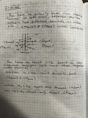
Real Surfaces (2-sided, Opacity=1). I only do this if it makes modeling an internal vacuum boundary quicker, and only if you don’t texture it to measure flux, pressure or density as it will be meaningless since these most likely will be different on both sides. See comments on analysis surfaces below. Some models I do have symmetry to both sides so doing analysis is valid in those few cases.

Analysis Surfaces (1-sided, Opacity=0). I used this if I want to see what the flux is from one direction in some place inside the vacuum boundary or right in front of a real surface. I also might want to know what the contribution is to the density or pressure just from that one direction.

Analysis Surfaces (2-sided, Opacity=0). I used this if I want to measure the total density. It can be used for pressure too but only if you know the pressures are the same in both directions, otherwise the pressure is directional and will be different depending which way you look. I know people who have made this mistake and got wrong answers.

Semi Transparent Real Surface (2-sided, 0<Opacity<1). This is to simplify not having to CAD a real 3D grid or mesh. However a better choice is to use…(Two 1-sided, 0<Opacity<1). Place the two 1-sided facets back-to-back (normals opposite) set with the same opacity. However, leave a very small gap between the two, like 0.001cm for example, otherwise it seems Molflow has a problem deciding which facet it is hitting and can count wrong and it will also display weird. This allows you to see real differences in pressure, flux and density from either side. You can also do the same thing for an analysis surface too, if for example you want to see the directional pressure from both directions at the same time.

Dear Alan,

Thank you again for spending considerable time with your explanations.

First of all, sorry for my previous comment - you’re right, whereas the term <1/Vperp> is the same, when multiplied by Nhits one gets the double density correctly.

I have cleaned up the code to remove the double-counting and the correction factor to compensate for the double counting. This is just a code clean and does not change the results, let me explain.

Now commenting on what you wrote:

For this simple example we are assuming the incoming and outgoing Vperp are the same. In many of my simulations they are not, which is why one needs to calc 1/Vperp for all the incoming and outgoing particles seperately and use the above formula rather than your double counting with correction scheme to accurately calculate the density.

This is important to emphasize: I did already count the incident and rebounding particles separately (I did not assume specular reflection or same outgoing velocity). I did not double-count the incident particles.

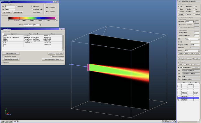
Proof (with 2.9.24, so without any modification to the code you have): I am creating 300K particles on the left and shoot them on a 300K target (right, selected). The density is 3.4E20 1/m3.

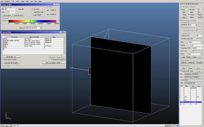
Now the only change I make is set the target to cold (10K), but keep the source hot (300K):

The density increased to 1.3E21 1/m3. So Molflow correctly measures that the rebounding particles are slower and thus increase the density. (For the record, setting the source to 10K as well increases the density even further).

Analysis Surfaces (1-sided, Opacity=0). I used this if I want to see what the flux is from one direction in some place inside the vacuum boundary or right in front of a real surface. I also might want to know what the contribution is to the density or pressure just from that one direction.

What you do is correct for flux and pressure, as they are vector quantities, and it’s perfectly normal to differ depending on the direction (or side) of a facet. Roberto and I, however, found that “density contribution from one side” is not really physical. Density is a scalar and should be directionless. With your “very thin sheet volume” explanation I get what you mean, but in the real world the thin sheet on either side of a facet whould have exactly the same density (as the thickness converges to 0).

I understand that the behavior you expect is that one-sided transparent facets each show half-half of the actual density (in an isotropic system) or in an extreme case (strong one-directional flux) 100% on one side and 0% on the other. My choice to avoid confusing users is to artificially double-count passing particles on…

  • One-sided transparent facets
  • Teleports
  • Structure links

These three types of facets are designed to receive hits from only one side. I want users on a teleport, link, and - while we debate this - also on a one-sided transparent facet to see the actual system density and not half of it. You would still get the correct “total density”, as you referred to it, on 2-sided (semi-)transparent facets. I understand that it’s confusing to see double the real density in your thread-starting geometry, but users would also be confused to see only half of the real density in a regular isotropic volume. I needed to choose between two wrong answers, and I decided to show the correct density in the more common (isotropic) case. My argument is that “density on one side of the facet” is not really a physical thing.

Finally, we are aware that particles can get stuck between two 1-sided facets if they are exactly in the same position. Due to numerical instability when solving determinants at double-precision, we believe there is no cure for that (in computer graphics it’s called Z-fighting:

image

Marton,

Thanks for your detailed reply,

Yes, even though it is a scaler, hence is directionless, you can still ask how much of the density came from particles in this direction. In my case, losses (scattering, ionization, whatever you define as a loss) to an energetic beam of particles from neutrals depend on the density and the cross-section for that loss. If you are trying to minimize these losses you can use the directional contribution to the density to help identify the source and how much it contributes. This can then lead to ways to minimize that source.

I agree you can debate which “wrong” answer is the least problematic. I would definitely side with the opposite position that it is less confusing and more self consistent to stick to your premise that 1-side facets ignore everything from the back side (which double counting breaks for those cases you mentioned) and realize that it is possibly ignoring contributions to the density from the backside. My systems are heavily pumped so even as a whole, my vacuum system is not isotropic, where most others are. However, even their isotropic systems will have local non-isotropic flows in front of their pumps or if you have long pipes. No matter which side you choose, documenting these differences in detail is the most important thing to do so the users are aware of the consequences. It’s easy enough for me to just divide the density by two in those cases. And just to be clear you are only doing this to the density, right? I have not asked how you calculate pressure on transparent facets which is another whole can of worms that deserve its own topic thread.

Thanks again for your update,
Alan

Hello Alan,

I had one more discussion with Roberto, and we decided to keep things as they are. It’s not to avoid doing some work (in fact, what you ask would be a few lines of change only), but we’d like to not confuse the beginner users. When they measure density on a wall, and get a number, they would be very confused to see half the density on a “probe” facet very close to the wall.

We kindly ask you, as advanced user, to keep in mind this correction, and if you use 1-sided transparent facets, divide the shown density by two.

I’ll update the “algorithm nehind molflow” document, or even better, I’ll make a dedicated web page for calculating physical quantities, when I’ll have the time.