Hi Molflow Team,
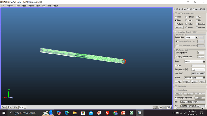
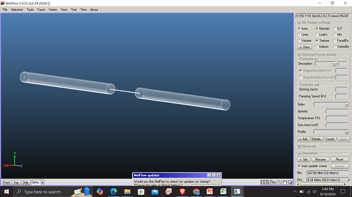
I am a new user trying to visualise the flow of atoms in an atomic beam. I have watched some starter videos and created a few geometries to do this. In one of these I have a high temperature cylinder, then a collimator having lower radius and lower temperature, then another tube with the same radius as the 1st tube but lower temperature. I have used cos^n desorbtion on the first facet with value 1E+05, opacity=0, outgassing = 1mbar, for last facet where final tube ends I have put sticking factor=1. All other facets have sticking factor=0.When I begin simulating, I am getting lines in between two tubes for much higher radius than the collimator radius. Can you please explain this and help me to correct it?
I guess you have leaks due to the incorrect orientation of some facets, but I can’t say anything more base on the screenshots alone. Turn on leaks display, if you can’t find any, attach the file here and I’ll have a look.
Thank you for your help. When I turn on leaks display there indeed are unwanted leaks on the inbetween facet where tube ends and smaller collimator starts. Which kind of incorrect orientation can cause leaks like this?
Check that the facet normals are pointing towrads the vacuum part, not outside. You can enable normal view for selected facets on top right. Check the “sides” section of this page: Documentation: Facet parameters | MolFlow+ and SynRad+
Thank you very much for your help. This was the mistake I made.

