I’m setting up a study with Molflow and I want to study the difference of emission when there’s a uniform or cosine reflection in a facet.
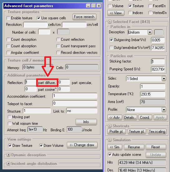
I saw that on the current version it’s possible (under Facet > Adv > Additional parameters) to set a certain % of diffuse, specular and cosine^N reflection.
Does this mean that the diffuse reflection (the default one) is a uniform distribution? According to an old forum thread it looks like “diffuse” is a cosine distribution, which would make it redundant. My confusion stems from there.
Currently running version 2508
Thanks in advance.
I see where the confusion stems from. Certainly a good question.
While you can change the distribution type for the desorption, you can not for the reflection. The latter is always a pure cosine distribution (part diffusive) or a cosine^N distribution (part cosine).
If there is particular interest for a choice of a uniform reflection type, I can discuss this with @maarton to implement this as a real feature.
Cheers,
Pascal
EDIT: Changed some confusing parts about cosine and cosine^N. Reflection is either of those: specular, cosine (diffusive) or cosine^N.
Hi @pbahr, thank you for your reply! (sorry for the delay, I was out of office yesterday)
It would be interesting to be able to set a uniform distribution. Just a curiosity, what happens if I set a 100% reflection with cos^0? Can it be considered uniform?
yes, 1 “part” cos^0 gives a uniform distribution.
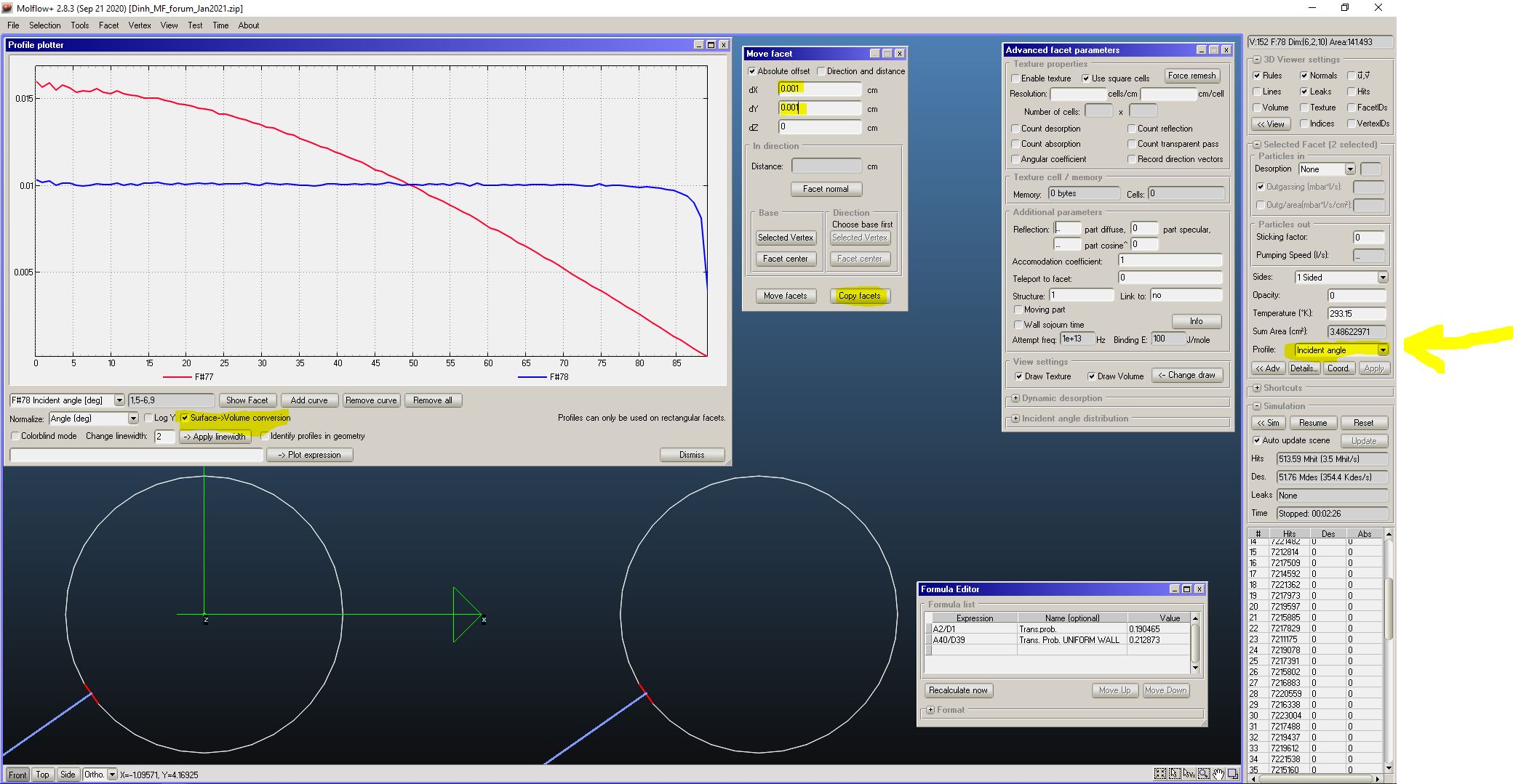
I’ve made a quick demo file: two R=1 cm L=10 cm cylinders, as in screenshot.
The one on the left is a “regular” one, with cosine generation at entrance (facet no.1) and cosine reflection along the walls, and sticking one at entrance and exit.
The formula window shows its transmission probability, A2/D1, which is correctly around 19% for a L/R=10 round tube.
The one on the right has cosine generation and sticking=1 at entrance and exit, but cos^0 reflection along the side walls.
The transmission probability is INCREASED, in this case, the uniform reflection would help increase the conductance, were it possible to implement (but, alas, it is physically impossible, there are theoretical studies on that, Kusumoto, JVST A, ~ 20 yrs ago).
I’ve also added to facets, transparent ones, by copying on each tube 1 facet and reverting its normal vector (pointing towards the wall, towards the facet from which it was copied), at a very small distance (dX=0.001 cm, dY=0.001 cm, using the move and then copy command in the “facet” menu). I’ve set the “pressure profile” on the two new facets, and selected the option “incident angle” in the menu on the right.
The angular profiles are shown: in red the angular profile of the “regular” tube, with cosine reflection, it is a cosine, as you can see… in blue the uniform reflection… apart from a small dip near 90deg reflection angle (which, if you think for a moment, is OK, since there can’t be enough molecules generated at 90 deg, those near the end facets with S=1 contribute less because they are pumped).
Cheers!
Hi @maarton, I’m trying to simplify a rather complex geometry for a vacuum study: imagine a vacuum chamber with attached about 20 flanges leading to 20 small chambers, all equal among them.
Simulating everything at once would be quite resources-heavy, so what I’m trying to do is to simulate every flange as a “black box” with an apparent sticking: I can model one single small chamber, and treat the interface surface as an uniform emitter with sticking = 1. From the simulation I can count how many particles will bounce back to that surface (thus reentering the main chamber). The apparent sticking will be given by (number of particles hitting the surface)/(number of particles emitted from the surface).
In the main chamber I can then model all those complex geometries as a rather simple one with a given sticking. The fact is that the reemission from every chamber will be uniform and not cosine-like.
I hope that the example was clear enough. I’m open to any suggestion to improve the study or in case I’ve made any conceptual mistake!
I don’t think so! The “re-emission” from each small chamber, if connected to the main chamber via tubulated connections, small flanges with short stubs, as usually done, will give an angular distribution of the outgoing molecules (out of the smaller chambers you don’t want to simulate entirely) NOT with a uniform distribution but rather more similar to a cos^N distribution, where the exponent N would depend on the geometry of the connection (and the smaller chambers too).
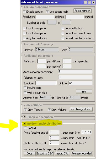
In fact Marton had introduced in the code the possibility to have desorption from facets as per an arbitrary angular distribution, it’s called “Incident Angle Distribution”, see attached jpg)
. This means you could study the angular distribution of each (or one representative) smaller chamber and then apply it to the facet corresponding to the common interface (like the circular opening of the connecting flange).
More details on this if you wish, with sample file.
Cheers.
Hello @rkerseva, thank you for the very informative replies! I think I’ll be able to consider a cosine re-emission for the pipes.
Just as a thought experiment, what if I wanted to apply this for two directly-connected chambers, with no pipe inbetween? Say for example that I have a very complex geometry I’d want to divide in two halves. Would each half-chamber see the other emit particles in a uniform matter or there would still be a cosine re-emission?
Depends on the geometry of the “very complex chamber”, there is no general rule.
In fact, only “very simple chambers” are usually used for theoretical/analytica studies in gas dynamics papers… like spherical chambers (Kusumoto’s article) and often circular tubes connecting infinitely large volumes… plenty of literature on that (ex. F. Sharipov and I. Graur).
It also depends on what you mean “would see”: if you place a flat transparent facet inside a system and use it to visualize the angle of incidence of the incoming/traversing molecules (like I’ve done in my example above) then it depends on how you orient the normal vector.
Remember, also, that pressure in molecular flow (which is the only flow Molflow+ can simulate correctly, i.e. a collisionless flow)… pressure is NOT a scalar quantity, it depends on the orientation of the facet you use to calculate it. Density, on the other hand, is a scalar, and Molflow+ calculates it correctly.