How do you calculate Pressure on transparent surfaces?

Following up on the discussion of how you calculate density, I wanted to ask how you do this for pressure on transparent surfaces. Technically, pressures only exist on real surfaces as a force per unit area and can have components perpendicular and parallel to the surface. On the microscopic scale these forces are generated from the change in momentum imparted to the surface from particles that go to and from the surface. The outgoing particles and hence the pressure will depend on the surface properties: Temperature, Accommodation, Type of Reflection, Sticking Factor, Outgassing Rate. None of which applies to transparent surfaces. The common vacuum definition of pressure would require the gas to be an isotropic MWB. So from this stand point, if you were to place the equivalent real surface at the location of the transparent surface, then I assume you would have to take for the transparent surface…

Accommodation = 0
Sticking Factor = 0
Diffuse Reflection ?

to give the correct pressure for the common isotropic MWB case. Does this seem correct? Of course the gas doesn’t have to be isotropic or Maxwellian, which makes the interpretation of the pressure less straight forward. This is why I tend to think in terms of density and shape of the velocity distribution. Less likely to make mistakes when surface properties (Temperature, Sticking Factors, and etc…) are not so isotropic either globally or locally.

I assume you completely ignore particles coming from the backside, which may give you a different pressure. What do you do for both transparent and non-transparent two-side surfaces? Do you take an average?

Best,
Alan
Hello Alan,

First of all, on real surfaces, Molflow calculates impulse changes on a microscopic level: it sums the orthogonal impulse changes (v_ort * gas_mass, separately for incident and rebounding) and the rest is just normalization (by facet area, number of physical particles per test particle, etc).

For transparent facets, our train of thought is similar: a transparent surface has no physical force acting on it, so technically the pressure is 0. However, I have to introduce an abstract quantity as users would like to use transparent facets as probes.

Since particles don’t change direction, speed, don’t stick, etc…

  • Teleport facets
  • Link facets
  • Transparent 1-sided facets

double-count the incident orthogonal impulses, or to put differently, sum the incident and outgoing orthognal impulses (which are always the same, as there is no interaction with the facet).

As two-sided facets always average back and front, the full list is:

  • 1-sided, opaque: count incident impulse, bounce/accomodate/thermalize particle, then count outgoing impulse
  • 1-sided, transparent: double-count incident impulse
  • 2-sided, opaque: for both front and back, sum the incident and outgoing impulses, and normalize by twice the facet area (i.e. average). Note that when you select a 2-sided facet, Molflow shows double the area in the Area textbox to make this evident
  • 2-sided, tranparent: double-count incident impulses from both sides, normalize by double the facet area (i.e. average)

Demo:

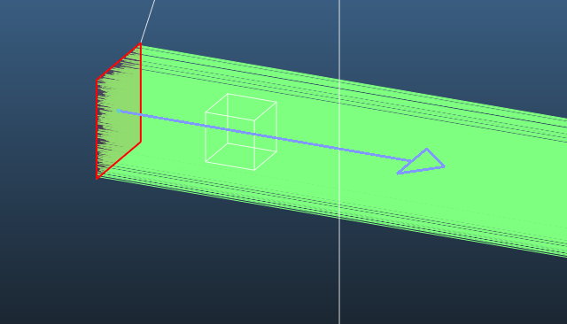
Desorbing from your system (jet of particles moving to right):

image

Sampling on 1-sided transparent cube:

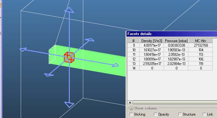
  • Near-zero pressure on five sides, normal pressure on side facing jet.
  • Double-density on side facing jet, normal density (2E17 except bad statistics) on four sides, 0 density on back side

Switching to 2-sided:

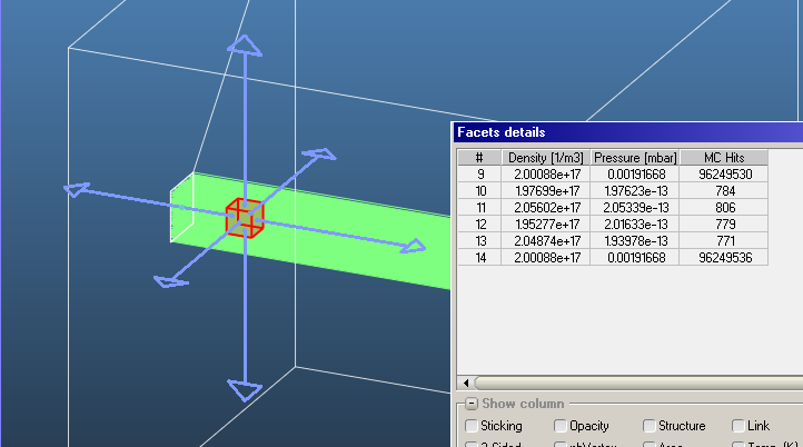
  • Pressure near zero on four sides (divergent direction), same on two sides (jet cross section direction)
  • Density is the same everywhere (2E17), regardless of orientation

Marton,

Double counting the change in momentum of incoming particles implies…

Accommodation = 0
Reflection = Specular

However, most real surfaces have Reflection = Diffuse, which could give a lower pressure. The biggest difference for the beam case above, and no difference if the gas is isotropic. However to make this type of reflection you would need to generate a new direction for the “reflected” particles and then use that to add to the change in momentum on the surface instead of double counting.

Most people don’t think of pressure being affected by the walls, because it is really used as a substitute for what should be the density. That’s just how it is taught, because it doesn’t matter for an isotropic MWB gas. It is not really taught in vacuum books what to do when this is not the case. This is why I often go back to the fundamentals of density and velocities distributions to keep from making mistakes in my more non-isotropic work.

I would need to think about it more, but I wonder what consequence this might have when you compare results from molflow to that from textbook equations for typical less isotropic cases like: in front of pumps or gas exiting long pipes. Are the equations making the correct assumptions? Is molflow? Maybe if you stick to working with density and fluxes rather than pressure you be fine?

Cheers,
Alan

Most textbooks start from the ideal gas equation:

pV=NkT

The outgassing (mbar.l/s in Molflow, or Pa.m3/s in SI) would be

Q = d(pV)/dT

So the equation becomes

Flux of incoming particles: dN/dT = Q/kT

Until this point there is no isotropy assumed.

However, most textbooks do assume isotropy as they go on:

For example, see this derivation:

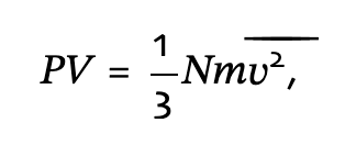
states

Screenshot 2024-08-13 at 13.24.53

Where does the 1/3 come from?

From the sentence “Because the velocities are random, their average components in all directions are the same” - and the author divides the square sum of components by 3.

In almost all derivations, there’s an assumption of isotropy. For example, we “all know” that the pumping speed is S=1/4 * <v_avg> * A * sticking
The factor of 1/4 is an integration over all incident angles assuming isotropy, finally making <v_ort> = 1/2 <v_avg>

In fact, even matching the molecule velocities to temperature is undefined. The “textbook” formula is that molecular energy is E=1/2mv2 = 3/2kT

The derivation is here: 27.1: The Average Translational Kinetic Energy of a Gas - Chemistry LibreTexts

And again, there is the sentence :

So again, they assume isotropy.

That’s why I’m proud that Molflow calculates pressure (and forces) using the true orthogonal components.

However, the non-isotropic effect becomes noticeable near strong pumps.

For example here, the incident velocities aren’t symmetric anymore, and the wall pressure is lower than the axial pressure (simple pipe with sticking=1 ends):

The pressure calculation is physically sound on side walls (the actual force, i.e. deposited impulse is calculated by Molflow), but as you say, “no change” i.e. no accomodation and specular reflection is assumed for transparent surfaces. In everyday terms, by “pressure in a volume” we usually mean the density, converted to pressure by the ideal gas equation. This is also what ionization gauges measure - the ionization probability actually samples the density, not a mechanical force, and software converts the value to a pressure. This can give false results when you’re sampling, for example a cryogenic system with a gauge that is at room temperature.

Replying to your last question, I believe MolFlow calculates all quantities correctly on walls, as it executes the elemetary physics (absorb incident impulse, treat molecule, eject particle to new direction). I even supported the edge case in time-dependent mode where the incident hit happens in one moment and the rebound at an other - in that case the incident impulse is correctly accounted to the first moment but the rebound to an other. For transparent, one-sided facets, I needed to do assumptions, hence our density and pressure thread on this forum.

Marton,

All of what you are saying is correct, but I think you were missing my subtle point that I was trying to make. The point being that the surface properties affect the reflected particles hence the pressure for non-transparent surfaces, but how does this translate to a transparent surface where the there are no surface properties! I would say the pressure should be what you expect if you put a real surface in its place, which 99% of the time it is diffusive not specularly reflecting. Double counting will effectively simulate specular reflection.

Specularly reflected particles will maintain the same velocity distribution as that of the incoming particles. If the incoming distribution is isotropic then the reflected will also be isotropic and double counting works just fine. If the incoming particles are a beam the reflected particles will also be a beam. But if you substitute in a real surface which is diffusive, it will change a beam like distribution into an isotropic one for the outgoing particles, and hence will lower the pressure.

In addition to the type of reflection, the accommodation coefficient will also affect the pressure. So what do you assume for transparent surfaces? Most assumptions made in books assume are that the surfaces and gas are in thermal equilibrium. So if you set the accommodation coefficient=0 for the transparent surface it should not change the energy distribution of the gas, so it will maintain its equilibrium to itself.

Do you see my subtle point that double counting may not give the correct pressure if it is defined as subsisting in a real surface. This approach applies to any kind of velocity distribution. While trying to use the everyday “pressure in a volume” of the density converted to pressure by the ideal gas equation doesn’t exactly apply for non-MWB velocity distributions.

BTW, I find this is an interesting topic to discuss because this is definitely outside of the normal vacuum textbooks. Your double counting is fine for the isotropic case, I’m just not 100% sure what the correct approach is for non-isotropic.

Best,
Alan