I have a question to consult,How to use Q/P to calculate effective pumping speed.
beng1.zip (102.7 KB)
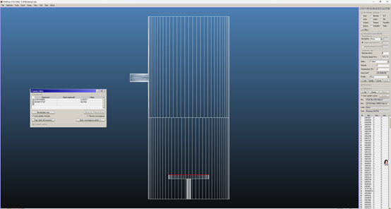
I used a model for verification, which is strange and not very consistent. As shown in the figure, the lower plane is used as the adsorption surface, the sticking factor is set to 1, the left small circular tube is used as the inlet surface, the gas flow rate is 1mbar L/s, and the effective pumping speed calculated using Q/P (P takes the inlet surface) represents the actual pumping speed.
Secondly, the most difficult thing to understand is why even if I change the adhesion coefficient sticking factor of the bottom surface, the calculated effective pumping speed will not change,Changes only occur when the sticking factor is very small
This question has been bothering me for many days, and I hope to receive your answer. Thank you very much
Hi:
you get meaningless results because your model has many problems:
-
There are two facets in the middle of the bigger cylinder, with opacity=1, i.e. solid, facets no. 38 and 107. Either you set them transparent (opacity=0), so that you can count how many molecules cross in one direction and how many in the opposite direction, or you can set the angular profile and see that the two directions have different angle of incidence profile in the middle of the cylinder.
-
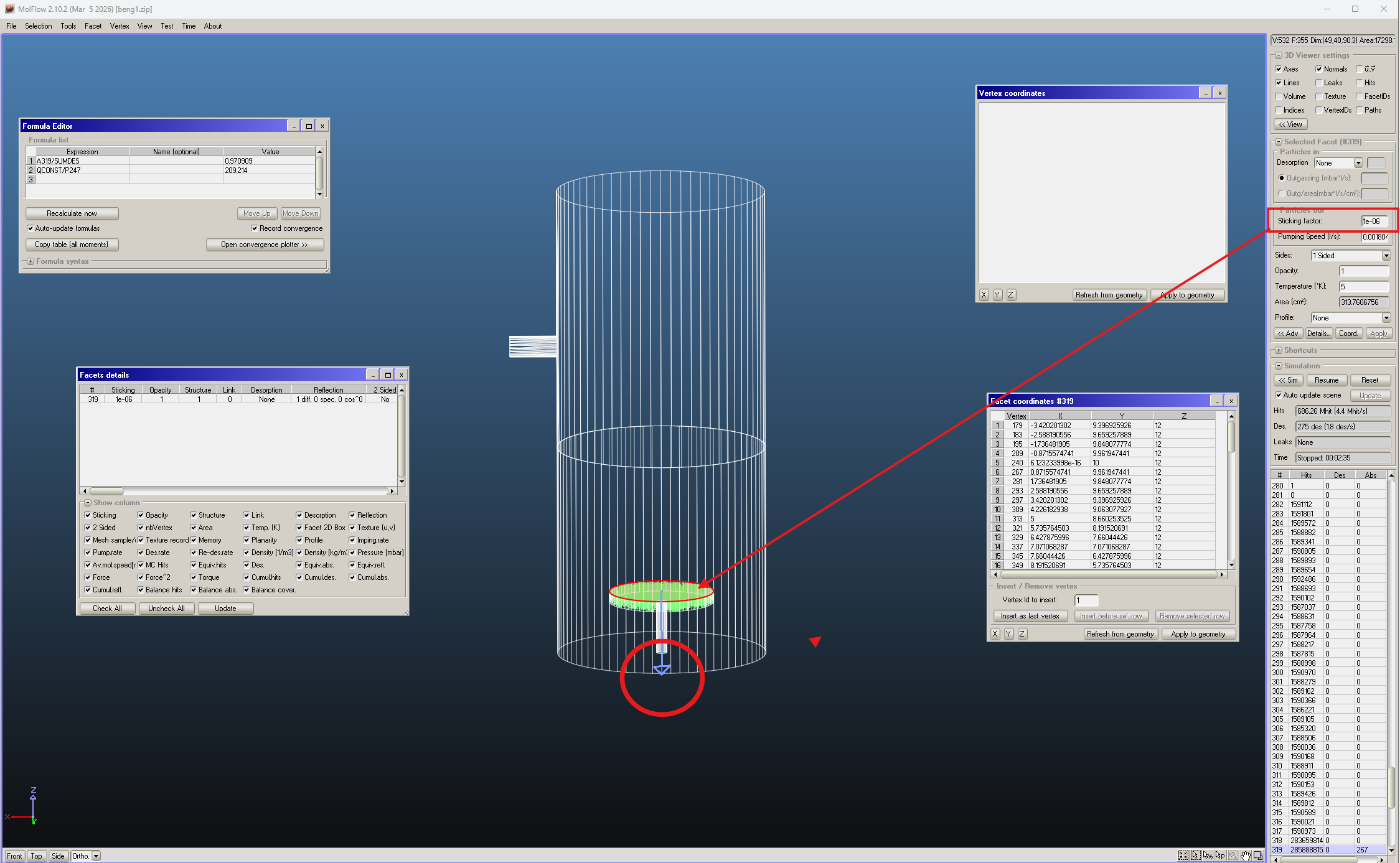
All the facets defining the pumping disc are oriented in the wrong direction, towards the INSIDE of the disc rather than the outside. If you set the sticking coefficient of facet no. 319 to 1E-6, so 1 M hits before being pumped on average, and check the box “Lines” in the “3D Viewer settings” pane (upper right of the screen) you’ll see what this means (screenshot 1 here). You should select all of the facets and use the CTRL-N command, shortcut of the “Facet”–>”Swap normal” command, to reverse them in one go.
-
You should remove the two facets 264 and 265, the ends of the thin support of the pumping disc, since they are co-planar one with facet 318, the bottom facet of the pumping disc, and one with the bottom of the cylinder, facet no.37. There should be no co-planar and totally or partially overlapping facets in Molflow (unless one or both have an opacity<1, i.e. at least partially transparent), or else you risk having molecules trapped, it happens especially from CAD-imported models.
-
Your cylinder/pumping plenum has many leaks!… it is made up of two halves, but the circular cross-section where they meet is not the same for the upper and lower halves.. so there are lots of leaks, which you can spot easily checking the “Leaks” box, upper right of the screen, and also the box “Volume” with the “Back only” box checked in the “3D Viewer Setting menu”… see screen shot 2.

So, these leaks must be removed, or else your simulation will have no meaning.
I take the liberty to do the modification on your geometry, using only one longer cylinder, instead of 2 halves. I include the zip file. I have deleted the lower half of the cylinder/pumping plenum and made the other half longer, down to Z=0 for all of its vertices. And added the “bottom lid” to close the system. Result is NO leaks, as intended… see third screenshot (sorry, the screenshots may appear out of sequence in this message).
If you change the sticking of facet no.244 (the pumping disc, now it has changed facet number as compared to you original geometry because I have removed the lower half of the original pumping plenum), you can see that the formula Qconst/P172 gives different pumping speeds. Beware that this is NOT the pumping speed inside the dome, it is a fictitious speed, since it is determined by the small conductance of the short tube which has the desorbing facet as its termination. In fact, when you set sticking=0.1 on the pumping disc, and an installed pumping speed of 180.4176 l/s, the formula gives a pumping speed Q/P BIGGER than the installed pumping speed, which is unphysical, I’d say. For the case s=0.01, the installed speed is only 18.04176 l/s but the formula gives 84.47 l/s, doesn’t make sense.
It therefore matters a lot where you calculate your pressure and effective pumping speed from the Q/P, which is correct only in open volumes, and it depends where in the volume. If you visualize the pressure along the pumping plenum you’ll see that it is not the same all along its length, of course: it is minimal near the pumping disc, and higher as you move towards the position of the short tube. Past that, the pressure stays constant, since there are no pumping facets on the opposite side of the cylinder/pumping plenum.
You can see it in the screenshot with textured facets, there’s a peak of pressure on the facets of the pumping plenum in front of where the short tube is located, because they are “beamed” out of the tube with a non-cosine-like angular profile, due to the non-zero length of the small tube (the longer the tube is, the more peaked near the normal vector is the angular profile of the molecules coming in… try it making the short tube longer!). I include here my modified version with textured facets, all of them, you can see the parameters in the “Advanced facet parameters” window, I selected all facets in the model.
Hope it helps, although I understand it needs some thinking in order to make sense.
If not, write back!
R.
beng1_MOD.zip (352.8 KB)

Thank you very much for your detailed explanations, geometry modifications and patient guidance. I have learned a great deal from your explanations, and now I clearly understand a series of problems in the original model, such as incorrect facet normals and geometric leakage gaps.
Regarding the unphysical phenomenon you mentioned:
“In fact, when you set sticking=0.1 on the pumping disc, and an installed pumping speed of 180.4176 l/s, the formula gives a pumping speed Q/P BIGGER than the installed pumping speed, which is unphysical, I’d say. For the case s=0.01, the installed speed is only 18.04176 l/s but the formula gives 84.47 l/s, doesn’t make sense.”
Through subsequent simulation investigations, I found that this abnormal phenomenon is related to the temperature of the pumping disc. The anomaly occurred because the pumping disc was set to 5 K. When I adjusted the entire cavity to a uniform room temperature of 293.15 K, the aforementioned unphysical phenomenon disappeared.
In addition, I have another core question to consult with you: under what conditions is the formula S=Q/P strictly applicable for calculating the effective pumping speed?
I have preliminarily verified by myself that this formula is accurate for straight cylindrical tube structures. However, once the model geometry becomes slightly more complex, the calculation results will deviate significantly. Could you please explain its applicable scope with simple model examples?
Moreover, I would like to ask how to calculate the conductance C of complex models in Molflow. According to relevant literatures, the effective pumping speed satisfies the formula S=C*Sin/(C+Sin), where Sin is the intrinsic pumping speed of the pumping disc. II don’t know if my understanding is correct. This formula can be used to further verify the effective pumping speed, yet I am unable to obtain reasonable conductance results through simulation.
Of course, I also cannot understand why the decrease in temperature of the adsorption disk would result in such a significant abnormality in the calculation of S=Q/P
Hi: glad to read that my reply/comments helped you. I am on a business trip until Friday, I’ll reply to this as soon as I.
I made two webinars about conductance calculations, from simple to (very) complex:
Thank you so much for your kind reply! Wish you a smooth business trip. I’ll look forward to your further response.
Thank you so much for sharing these two webinars on conductance calculations! I will watch them right away.
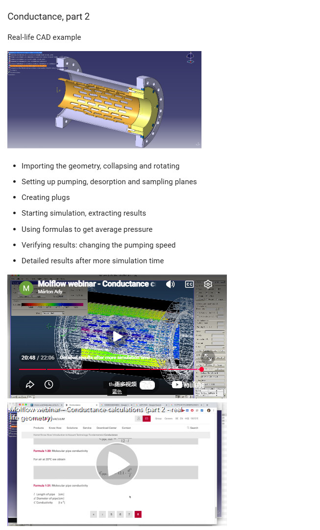
I would like to consult with you regarding the model in the webinar video shown in the figure.How should we calculate the overall conductance by using transmission probability multiplied by the conductance of the inlet surface?In previous straight circular tube models, the total conductance could be obtained in this way.I wonder if this method is also applicable to the current model.
The video’s goal was to show how you can calculate the conductance with the Q=dP*C formula. In this model, which isn’t linear, I don’t think you can use the other formula, there isn’t even an “inlet surface”.