Can anyone further descibe the inputs needed in the MAG file for the analytic expression? I have the period of the wiggler and the peak field (and number of periods).
To me it looks like the peak field is input as K2 but I do not know how to obtain the Kx input.
Also, how is the wiggler set-up if the input does not require either the length or the number of periods?
For example, a simple wiggler, going along axis Z with 0.5 Tesla peak field, and 25 full-periods of 3cm would look like:
3 0 0 1 25 1
0.5 0
Update: the number 25 should be deleted, it was there by mistake. The number of periods will be determined by the region length (75 cm / 3cm period = 25 periods)
The magnetic region that loads this file should be 75 cm long, and its starting direction (theta angle) should be found with trial and error so that its endpoint is still on the Z axis.
If you need an example let me know and I'll attach.
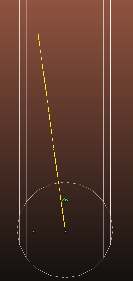
The "Analytic expression" has been ported from the original (DOS) version of Synrad. Upon looking at it closer, it contains the analytic expression for describing the magnetic field in a wiggler following the Halbach wiggler field model:
Where k=2PI/wiggler_period.
If you use the Halbach wiggler model: you choose "Analytic" as the X component in Synrad's region editor, and define the k, kx and B0 parameters in an external MAG file. The x,y,z coordinates are aboslute, so you'll have to position your undulator at the origin.
That said, so far we always used the Sine/Cosine approximation.
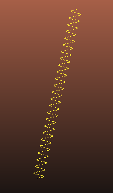
I was trying to model a wiggler using this method, I just realized the beam shifts on the x axis, speciall if the device get longer. Anu pther methods to simulate a wiggler?