Hello, I am working on a SynRad simulation that has NEG material in line with the synchrotron fan. I’ve looked but cannot find what to use as the proper inputs for the reflection properties. Any suggestions or ideas on where to find this information? Thanks!
Hello Paul, and welcome to the forum.
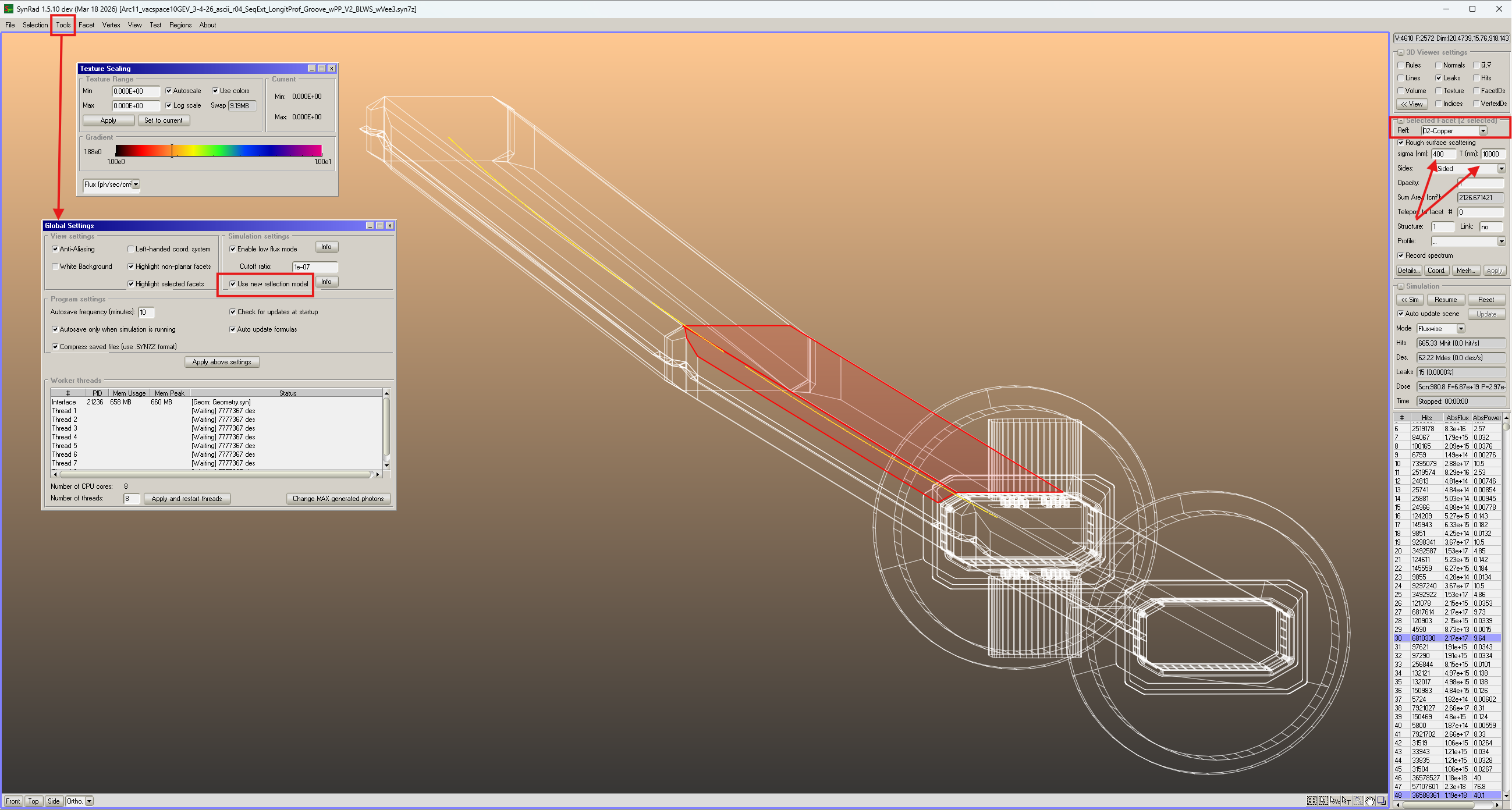
Once you have your 3D model ready and the beam trajectory files too (param files with, in case, mag files), you should select the relevant facets and assign to them the material properties you find in the pull-down menu “Refl.”, upper right of the screen, together with the values for sigma(nm) and T(nm) (autocorrelation).
Make sure you have the box “Use new reflection model” checked, in “Global Settings”, “Tools” menu… see screenshot.
The documentation on the web site should explain how sigma and T change the reflection properties. Smaller values of the ratio of the two give a smoother surface, if you play around a bit you’ll see it immediately, looking at the textures of a facet receiving a reflected SR photon fan.
Good luck!
R.
Forgot one thing: there is a limited amount of materials’ files. If you look for stainless steel you won’t find it. You can use the one for copper, the main difference being only the position of the absorption edge near 1000 eV, typical of copper. SS has several absorption edges, corresponding to the different elements on/near the surface, Fe, Cr, etc… but overall no big change compared to Cu unless you are interested in exactly the photons in a particular photon energy range. For a full spectrum the fact that the absorption lines are at different positions doesn’t change much the global reflection properties, it is more the surface structure (sigma and T) which rule that.
This statement is valid, of course, only for SR photons “not too energetic”, i.e. max few 10s keV. For very high SR photon energy, like in CERN’s FCC-ee tt machine with 1.4 MeV critical energy from the dipoles, the material of the chamber becomes very important, because the interaction photon-material is of nuclear origin, and SYNRAD+ cannot model that, you should use GEANT4 or FLUKA. Anyway, the part of the spectrum below, say, 100 keV (beginning of Compton edge in Al, Cu is around 200 keV) can be modeled with SYNRAD+, successfully.
That’s all. Cheers.
Thanks Roberto! I was actually unaware of the “new reflection model”, good bit of information. I’ll have to play around with that.
But I was more looking for the material files for NEG (be it either Ti-V-Zr or Ti-Al (Zao)), or if anyone has attempted to model this material and found something that’s close enough. Following the links through the Materials Reflection Tables on the website didn’t wield any information.
To give some context, in lieu of a traditional absorber due to geometric constraints, I am looking at shielding the wall of our aluminum chamber with NEG to take advantage of its ability to attenuate secondaries.
Hello Paul:
There have been very few measurements of NEG reflectivity, mainly because it is a difficult experiment, needing specialised beamlines which are often fully booked and difficult to get beam time on them. There is one at BESSY-II that we at CERN used for characterizing the reflectivity of the sawtooth profile for FCC-hh and LHC, and we planned to do it also for NEG for FCC-ee but never managed to do it. NEG coating has, as you know, different morphologies too, depending on the deposition conditions and the substrate surface, and therefore one would need to carry out a comprehensive series of measurements for different NEGs. Anyway, what I do is to use Copper reflectivity, and play a bit with the roughness parameters sigma and T. NEG is certainly not ultra-smooth, as a surface, keep that into account. Coming to your last sentence, NEG coating will attenuate some secondaries but at the same time will generate X-ray corresponding to some emission line of Zr (or is it V?), in fact this is used as a diagnostics to measure the uniformity of the deposited NEG-coating. At the ESRF, and I think also elsewhere, some ID chamber with 1mm thick wall (extruded Al), elliptical opening of 57x8 mm2 (HxV) have damaged some plastic components near the ID due to this emission, but that was on a particular ID, I think it was a wiggler… so it may not apply as a general rule on all machines and IDs.
OK; I stop here now.
If you wish you can write to me at roberto.kersevan@cern.ch or rkersevan@bnl.gov, I am consulting for EIC..
Roberto, very fortuitous that you are consulting with EIC, this simulation I’m working on is actually for the BAR (Brookhaven Accumulator Ring)!
Understood on the complexities of what I’m asking for, it makes sense that there’s not a “one-size-fits-all” reflection curve since NEG is so varied and complex. Starting with copper and tweaking with the parameters is a good starting point however.
I’ll reach out sometime next week once I play around a little bit. Thanks again!