I want to simulate the environment of a CubeSat on low earth orbit so the free molecular flow simulation in Molflow does help me but I wanted to ask if the use of Molflow is limited to simulating free molecular flow within a chamber or can it also analyze the pressure distribution of the flow around an object placed inside the chamber?
Hello Daniela, and welcome to this forum:
You can simulate anything which can be ray-traced with “bounces” following angular distribution of the reflected molecules which follow the distribution as per cosine, cosine^n, mirror or combination of them.
Molflow+ has a built-in feature simulating translating facets and rotating facets, so you can even simulate the cubesat in orbit, with the background gas (outer layers of the atmosphere) moving “against” it with its orbital velocity. I have modeled in the past some test chambers with ion-engines and their plumes, assuming molecular flow conditions prevailed, just for fun, taking details from literature papers.
Thank you very much for the reply!
Could you please indicate what is the name of the built-in feature that simulates translating facets and rotating facets? And if there is a particular video that shows this feature? I am trying to simulate a CubeSat in a very low earth orbit in order to estimate the pressure and drag on the body due to the free molecular flow. I started by designing a CubeSat of 10cmx10cmx10cm inside a tunnel of 30cmx30cmx70cm.
Hello Daniela,
You’re looking for the “moving parts” feature, in the Tools menu.
You can enable it for individual facets in the facet advanced settings (pop-out pane).
I’ll send some screenshots tomorrow from my office Pc,
Cheers Marton
Hello Daniela:
I’ve made up a quick geometry: a 10cm edge cube inside a 30x30 section x 70 cm long box (maybe that’s not what you meant, can be changed easily).
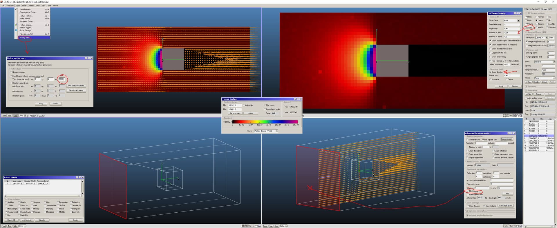
As you can see in the attached figure, I have also added a transparent (opacity=0) facet in the middle of the model, with 1x1 cm2 texture elements, and visualization of the average velocity vectors in each texture elements (you can select this option via the “3D Viewer Settings” checkbox, in the “View” button , upper right corner). I have set a unitary desorption from facet no. 7, on the “tunnel” box, which has a 5 km/s relative movement in the +Z axis direction (probably it should be bigger in low-earth orbit, right?). I’ve set the angular desorption (when facet no.7 is considered at rest, as cos(theta)^500, so as to have parallel traced molecules. I’ve also set to 1000 K the temperature of the desorbed molecules, and mass 32 as the traced gas (O2… or should it be atomic oxygen, mass 16? I leave that to you).
You can see the result: there’s a “cone of silence”, or whatever you call that, downstream of the cube.
If you select facet no.1 (the facet of the cubesat facing the direction of motion) you can see in the “Facet details” window the value of the pressure on it. You could texture it, even just one big element, and see the pressure vector… which could be useful if you tilt a bit the cubesat and want to determine the rolling torque. I’ve tried to visualize the molecular speed ON facet 1, by setting the “Profile” type to “Speed distribution” but I get an empty diagram, don’t understand why, I’ll talk to Marton tomorrow… there may be a small bug in the routine… if so he’ll fix it.
So, summarizing (in case it was not clear already): the cubesat is steady, and the external “tube” moves at 5000 m/s in the +Z direction. All 6 facets of the “tube” have sticking=1, so that when a molecule reaches them it is removed (so simulating an infinitely large space, with no return for molecules, seems OK to me).
Let me know what you think of this, and then we can workout further details later. Also, there may be a way to calculate the drag force directly, Marton may be telling how to do it (I’ll talk to him first).
Forgot to add the Molflow+ file I’ve created, here it is in attachment:
cubesat10cm.zip (115.1 KB)
Hello Daniela,
I’m just chipping in to Roberto’s answer. During a collaboration with a space player we did a modified version of Molflow that can caluclate molecular force (and torque) on a body. It is exactly the same as the regular Molflow version, but there are additional quantities that can be added to the Formula Editor (namely: force and torque on a single facet, or a set of facets, and their X,Y,Z components). In exchange, the simulation speed is around 20% slower, that’s why it’s not in the public version. Let me know if you need it.
Cheers, Marton
Thank you very much for all the information! I just had the chance to revise everything and will follow the implementations you, Roberto, did. I want to know if it is possible to get the drag force directly as mentioned by Roberto. Also, can I have access to the modified version of Molflow that calculates molecular force? I will still use the simulation with the public version but I want to try the one mentioned by Marton.
Also, Roberto, were you able to figure out why you couldn’t see the molecular speed on facet 1?
In addition, I’d like to ask, what is the difference between setting the profile as speed distribution in facet 1 vs setting that in facet 13? Is it like setting the inlet condition? Because my first thought was that if I set the profile as speed distribution in facet 13, it would show me the profile of the speed distribution simulation on the plane of facet 13. Maybe I’m misinterpreting the function of that profile function.
I tried implementing the model Roberto did but I cannot get a pressure distribution on the facet intersecting the CubeSat (i.e. the transparent facet in the middle of the model). I am uploading the file, if you could please check it out let me know. Also I set the gas molecular mass as 16 g/mol and T=500K.
Cubesat.zip (57.8 KB)
Dear Daniela,
Replying to your previous message, I have incorporated the molecule force features to the beta version of Molflow.
Download link: Release v2.9.8_beta · molflow_synrad / molflow · GitLab
Instructions for the new function: Measuring molecular forces | Molflow+
I’ll have a look at your file.
Concerning your file, I saw two mistakes:
- The large transparent facet was opaque (opacity=1), and texture was set to count “transparent passes”, i.e it was not counting reflections. Fix: set opacity to 0
- The cube’s sides were pointing inwards, and they were 1-sided (catching hits only from the normal side). Fix: select the six sides and swap normals
Then the simulation runs fine, both with textures and direction vectors.
Attaching fixed file.
CubeSat_marton.zip (113.4 KB)
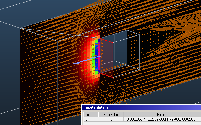
By the way, in this hypothetical setup, the molecular drag force on the front facet is 285uN.
Hi Roberto and Marton,
I am still configuring the setup for the CubeSat simulation in very low earth orbit. Last time, the simulation gave a very low drag force on the face of the CubeSat (0.000285N) as the max on the front face so I am still playing with the Molflow setup to move away from this theoretical result. Nonetheless, I am slightly confused with the Desorption options for the “Particle in”. I was following the Molflow webinar that modeled a simple vacuum chamber, and in it, all of the facets, except for the pumps, were configured with the desorption of cosine distribution. I was wondering if this would be the case for the CubeSat walls in the simulation. If I define a cosine distribution of the desorption on the walls, would that mean that the particles are hitting with a cosine distribution but not actually getting inside the CubeSat? Also, what is the difference between “Cosine”, “cosine^N” and “recorded” desorption in the “Particle in”?
I am following the Molflow+ file Roberto created in December.
Thank you.
Hello Daniela and happy new year!
You are asking several questions, I’ll reply them all hoping that you won’t be confused by too much info ![]()
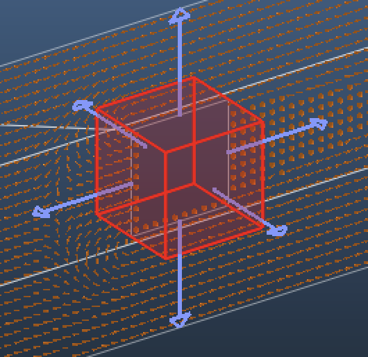
- By default, facets are one-sided (so are the CubeSat walls in Roberto’s file). When such one-sided facets desorb, they emit particles only towards their normals - in this case outside the cube:
In Roberto’s simulation, only the existing outgassing creating the pressure in space was modeled, from a single outgassing facet:
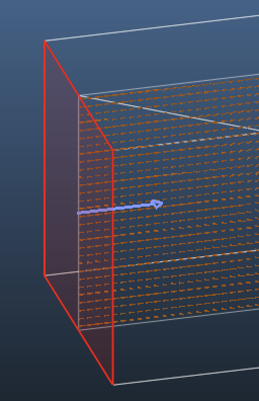
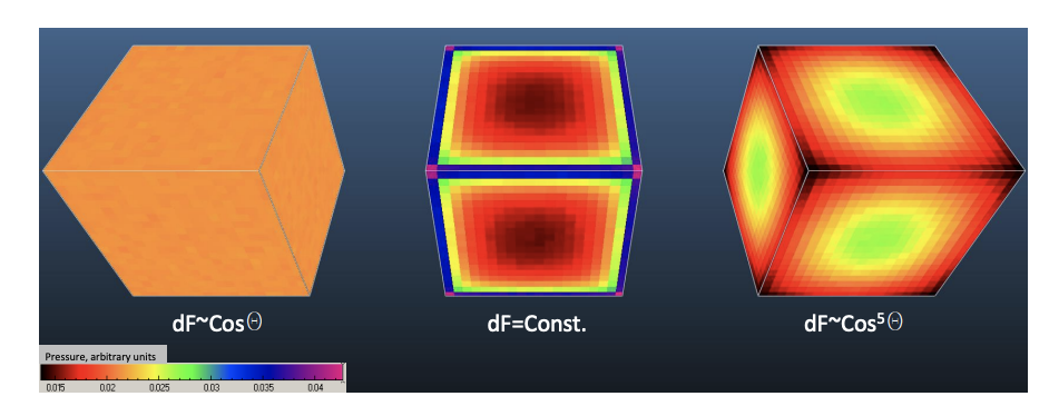
This facet had a Cosine^500 directional distribution, meaning that the probability of a particle being emitted in angle theta with the normal direction is proportional to Cos^500(theta)*sin(theta). In practice, a Cosine^0 distribution is uniform, a Cosine^1 distribution is Lambertian, and a Cosine^2 is slightly more peaked towards the normal, and Cosine^500 is very peaked - almost all particles move towards the normal direction.
In the special case of moving facets, a Vz=5000m/s component is added to the velocity vector from the desorbing facet, further peaking the directional distribution.
In case of your simulation, where the frame of reference is moving with the cubesat, the thermal outgassing from the cube is simply Cosine, whereas the space’s “outgassing” is also cosine, with an added Vz component to account for movement.
The Recorded option is only available if you pre-sample a directional distribution with Angle maps.
To summarize:
- All emitting facets (space and cube) should be cosine
- The particles desorbing from the side facet (representing residual pressure in space) will have a vz=5000m/s component added
- Because of that, the incident directional distribution on the cube will be near perpendicular
As for the low force measured, it is correct with the current settings:
![]()
A 0.01m2 surface with 0.027 Pa force will indeed mean a 0.00027N force.
Be aware though that this result scales directly with the outgassing on the space facet, which is simply set to 1mbar.l/s. Setting it to 10 times higher will increase the force 10-fold. You have to increase this outgassing value so that it correpsonds to the pressure in space that you’re modeling. Let me know if you need help how.
Cheers, Marton
Thank you very much Marton for your prompt response!
When you say that “the thermal outgassing from the cube is simply cosine” you mean cosine^1? In my model, I am setting additional parameters for the CubeSat’s faces in the “Advance facet parameters” to be Reflection: 0.95 part diffuse, 0.05 part specular and this sets 4.16333-17 part cosine^0 automatically, thus I assume that by setting the 0.95 and 0.05, the cosine distribution for the walls of the cubesat become negligibly small (e-17), would that be the case?
Also, when you say “space’s outgassing is also cosine” you mean cosine^1?
Regarding the outgassing, I wasn’t familiar with the fact that I need to specify this quantity for the simulation. I thought it specifying the conditions such as temperature, among others, would suffice but for VLEO I am not sure what quantity would satisfy the model. I would need to search more on that. If by any chance you’ve dealt with setting the outgassing for VLEO simulations, let me know!
I am attaching the model I have with the CubeSat facets defined with diffuse reflection at 0.95 and thermal accommodation coefficient of 0.95.
Cubesat.zip (118.8 KB)
Best,
Daniela Mata.
For your first question…
- cosine^0 is “uniform” (equal probability for all directions)
- cosine^1 is “diffuse” or, indeed, in our words sometimes simply “cosine”.
So in your case 0.95 is “diffuse” or “cosine”, and negligibly small is “uniform”.
In any vacuum system in equilibrium, including space, the directional distribution is cosine^1. (As validation, in my thesis I mentioned I explained that any other distribution would result in molecules accumulating or depleting in corners:)
You can set the correct outgassing rate by trial and error (or by scaling, as in ultra high vacuum everything is linear): since at 5000m/s the reference frame’s speed is much larger than molecular speed, you need to make sure that the molecule flux entering through the outgassing facet equals the molecules in space in a 5000m*A volume body, where A is the outgassing facet area.
You can use the ideal gas equation, and Molflow also displays the impingement rate in Facet Details.
Thank you for the reply Marton. Regarding the outgassing rate, I think I’m still unclear on the set-up you explained. Did you mean that I should know the number of molecules in space in order to set up the outgassing setting such that it is = molecules in space5000m/sA ? A being the outgassing facet.