Question: Calculate pump time

Hi

I have a question about time dependent vacuum simulations.
I have a small chamber inside an outer vacuum chamber, with only a few small openings. I want to pump out the inner chamber, and wanted to simulate the time it takes to get to a specific preasure starting at normal preasure. So that i can estimate if i can get to the preasure in reasonable time or if i need more/bigger holes in it.
Is this possible with Molflow? I found this article: https://molflow.web.cern.ch/node/214
but i think that is not what i am looking for, i can’t find a way to set a start preasure or am i missing something?

Thanks in advance
Tobi

Dear Tobi,

One of the core principles of Molflow is that in can only generate, reflect or absorb molecules on surfaces (and not in the volume). This is the reason that you can't set a starting pressure: that would require recognizing "valid" space between the facets and uniformly fill it with initial particles.

In theory, you could create such an initial condition by injecting some particles for a very short burst (controlled by parameters, as described in the time-dependent mode), closing injection and waiting until gas reaches equilibrium, then open the holes leading to the outer chamber and plot the pressure decrease.

I would advise against using this approach though: in time dependent mode all hits are simulated, so it is suitable up to processes taking a few seconds (few million collisions) but not longer.

Luckily for you, your problem can be solved easily if we go back to vacuum theory :)

If you have an inital pressure p(0) in a volume V and the pumping speed is S (everything in SI units), then the pressure evolution will be:

p(t) = p(0)*exp(-t * S/V)

The S/V is the time constant of the system: basically the faster we pump (S), the faster the pressure decrease will be, on the other hand the larger the volume is (V), the slower.

You know already p(0), the target pressure, the volume V, so to get t you need the pumping speed S.

Basic UHV vacuum theory says p=Q/S where Q is the outgassing in SI units

It means the more you pump, the lower pressure you'll get, and the more you inject, the higher.

Do the following: forget Molflow's time-dependent mode, do a steady state simulation:

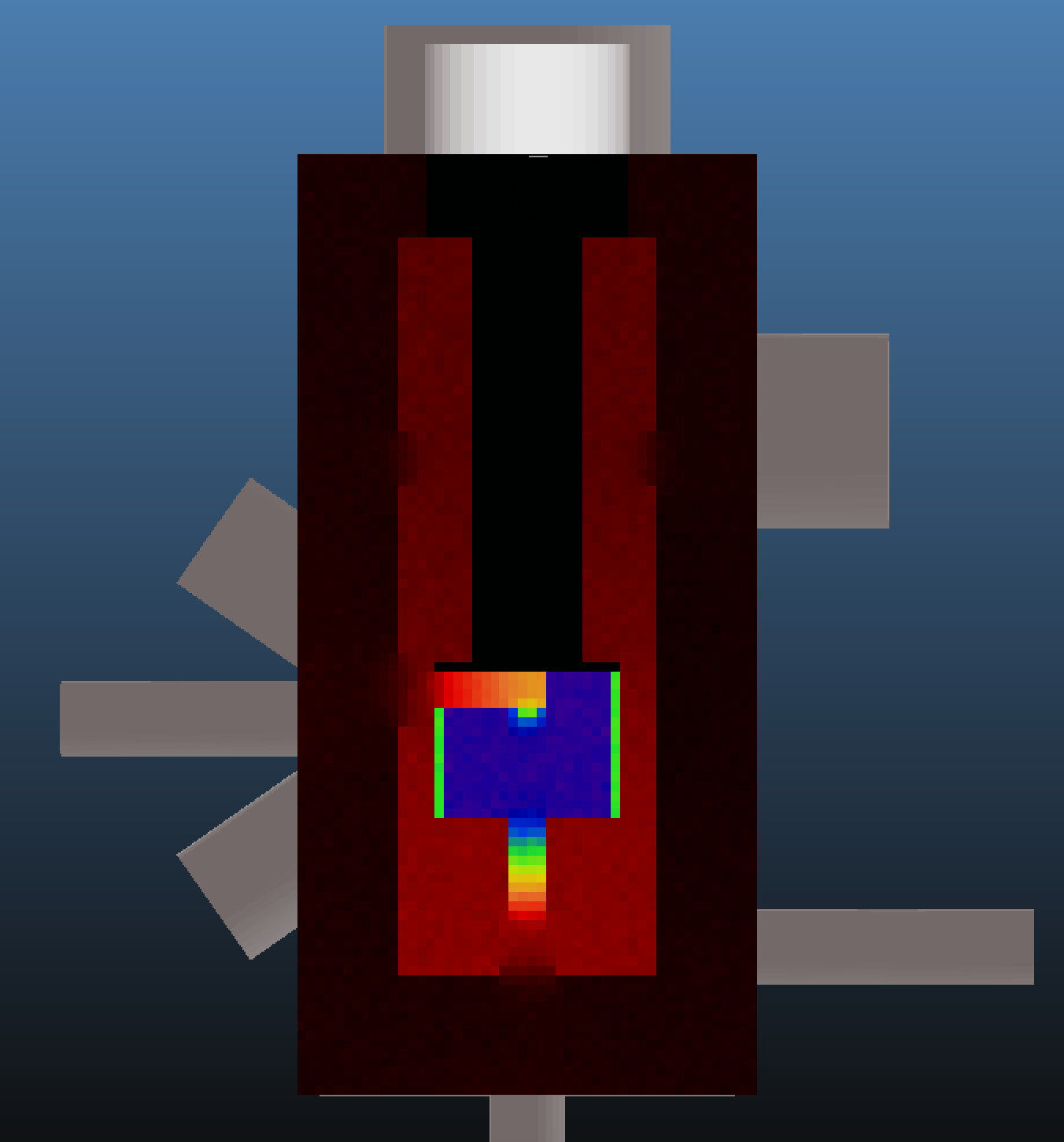
  • Set uniform (per area) outgassing to your inner chamber walls. The absolute value doesn't matter as long as it's uniform.
  • Set pumping in the outer chamber with the real pumping speed of the simulated system
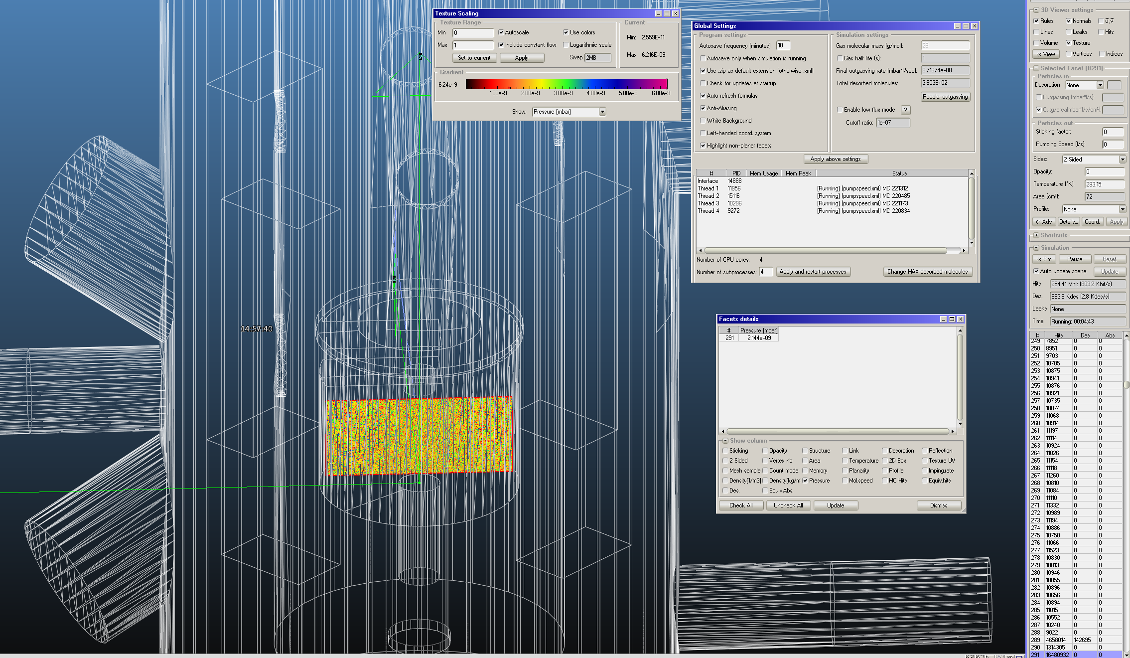
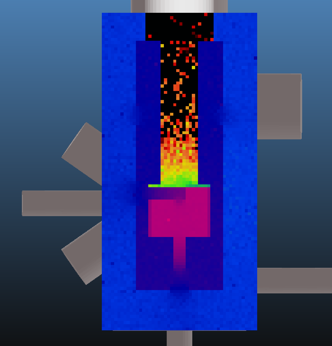
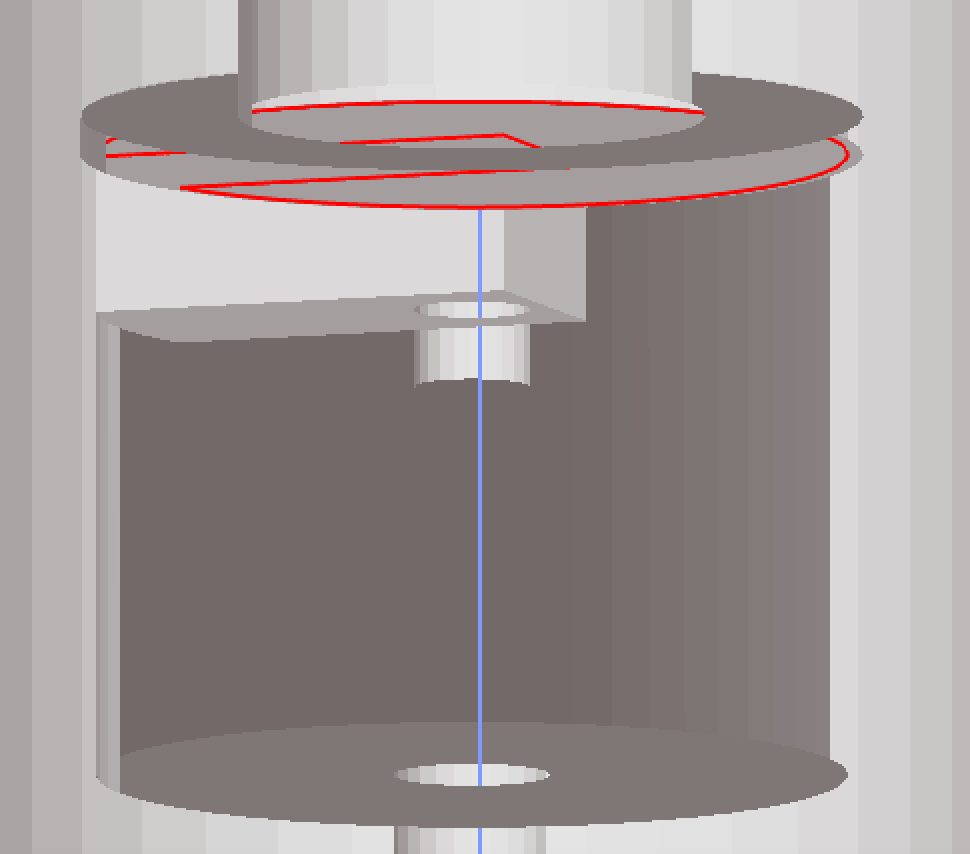
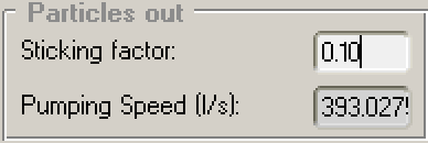
  • Run the simulation and see what pressure Molflow calculates in the inner chamber. For this you can create a large transparent facet in the middle.

Then you'll get the effective pumping speed of your outer pumps in the inner chamber. You know Q (the outgassing sum, you can check it for example in the Global Settings window), you just calculated P, therefore you'll get S.

Plug that S in the first equation and you'll get the pressure solution of your system.

Hi

Thank you for your detailed answer, this realy helps. Thats what i thougt. I will try doing the calculation you discribed, i already did a steady state simulation, so it should be easy to calculate.

Hi, i kow this is an old thread and i had to make a new account because i couldn't access my old one, but i tried the methode explained to me above again to calculate the pumpe time of a simmilar setup with a small chamber with only a small opening inside a regular vacuum chamber.

The regular vacuum chamber had 4 NEG pumps and one IGP. I set the surface of the inside chamber to a uniform outgasing and divided the final preasure in the inner chamber total the outgasing in the inner chamber by the and got around 6 l/s pumping speed (the 4 NEG have a pumping speed of 430 l/s each and the IGP 100l/s). Then i tried to calculate the time it takes to pump from 10^-8 mbar to 10^-11 mbar with the volume of the inner chamber. As this volume is under 1l i got something around 3 seconds, which doesn't seem correct.

Do i have to take into account, that the pumping speed of the NEGs changes with the reduction of the preasure or does anyone know where i dit a mistake, i am thinking over this for a few days and can't find what i did wrong.

Help here would be much appreciated.

Upload the geometry here and I'll have a look.

Thank you for your help, unfortunatly i had to use an other account again (this time my github account) because since the new design of the Forum i can’t login to the forum anymore. On the molflow website it works, but not on the forum. ( i already wrote the helpdesk).

I uploaded the Molflow file, with some memorized selections, and the STL files here:

https://ikpcloud.ikp.physik.tu-darmstadt.de/index.php/s/UG0KSdQ3NHr9AvU

The model is an outer Vacuum chamber with 4 NEGS in it, then there is a heat shield, and an inner smaller chamber, which later will be cooled to cryogenic temperaturs. This is an approach for a electron source with increased lifetime.

when using the stl files you need to delete facets of the 5 holes of the heatshield and the two in the inner chamber, my CAD software wouldn’t allow this.
In the Molflow file i also created a measure plane inside the inner chamber.

I looked at the file. Can you set up the physics of the system and re-upload it? The Molflow file is enough.

  • Add the IGP’s sticking as I don’t know where it is
  • The current NEGs’ sticking is around 400l/s, just making sure they are correct (0.1 sticking factor)
  • Can you add outgassing to the inner chamber? It’s not clear whether you’d like to outgass to the inside, to the outside or both. Currently the facets are 1-sided to the outside.
  • Can you tell me how you calculated the 6l/s pumping speed, and the 3s pumping time?

Thank you, Marton

(PS I’ve merged your old account to this one)

Ok thanks, i reuploaded it, 1 made the heatshield and the inner chamber 2 sided and applied an outgasing on the inner chamber. As i made the inner chamber wall only one facet to keep the model simple i think the outgassing is in both directions when i make it two sided. Is there a way to make the facet two sided for particle reflection but only outgasing in one direction? Anyhow i applied a uniform outgasing of 1e-10 /cm^2 and get a total outgasing of 9.7e-8. I applied a stickingfactor of 0.1 to the neg pumps which is what molflow caluclated for a pumpingspeed of 430l per NEG and nitrogen. Also i applied a IGP (large tube on top) with 50l/s. then i started the simulation. On the facet in the inner chamber, where i set the opacity to 0 to only use it to determin the pressure i get a final vacuum of 2.1e-9. When i use the formular S=Q/p to calculate the pumping speed i now get 44.7 l/s (don’t know why i get i higher value this time). If i take into account that the outgasing is two sided and devide the outgasing by 2, i get around 22.3/s which i still can’t belive as the inner chamber only has two small holes.

I then used your second formular p(t) = p(0)*exp(-t * S/V) to calculate the time. i get t=-V/S * ln(p(t)/p(0)).
Here i used the volume of the inner chamber which is around 0.57 l. If i use the 44.7 l/s and lets say p(0)=10e-8, after the turbo pump to p(t)=10e-10 i get 0.029 seconds. Which seams really really fast. i can’t belive this is right. But i can’t find where i made the mistake. If i take the 22.3 l/s i still get a very small number ob 0.58 seconds.

Here is the file:
https://ikpcloud.ikp.physik.tu-darmstadt.de/index.php/s/43HkU1jBxYIRtgJ

Thank you for the detailed explanation, it’s very clear now.

If a facet is 2-sided, it is outgassing at both sides. This has resulted in particles going a little bit everywhere:


(particles shouldn’t be in the black area).

I flipped the side of this facet so it outgasses towards the chamber:

And changed these to 1-sided so they also outgass towards the chamber:

Now the pressure profile looks better:

The NEG pumps are 390 l/s for me:
Screen Shot 2020-05-18 at 5.38.45 PM

The pressure increases slightly because of these changes to 3.15E-9 mbar.
This gives an effective pumping speed of 9.7E-8/3.15E-9=31l/s

Which, plugging in to the equation, gives a short pumpdown: t=V/S * ln(p0/p1)=84ms

Please note that this pumpdown time assumes the pumpdown time when there is no gas input. If you have a background pressure due to outgassing, this pumpdown will be true for a pumpdown from 1e-4mbar to 1e-6mbar, also from 1e-5mbar to 1e-7mbar, but NOT from 1e-8mbar to 1e-10mbar, since the background of 3e-9mbar is larger that 1e-10mbar. When there is outgassing present that creates a background pressure, it means that pumpdown to the target pressure will take 84ms.

In your real-life case, the background will decrease slowly, as the surface decontaminates, and may take hours. The outgassing rate will decrease, while the pumping speed will be more or less the same through the whole process. NEG saturation is not important for a volume of 0.57l. It means that the characteristic response time of your system (~90ms) is much faster than the change of the surface properties. Therefore the process governor will be the cleaning of your inner chamber, and this cannot be calculated with Molflow (it depends on the surface history, the contamination type, etc.).

Hope I’ve helped, even if it doesn’t answer your original real-life pumpdown time.

Yes the NEGs is not 430 l, i put that value in and rounded the stickinfactor down to be on the save side.

Thank you for your time, this helped, even if it doesn’t answer my original question but now i know that i need to do a experimental measurement to get the real pump down time.

Hello,

Going back to this old threat, I am facing a similar problem.
So what would be the best way to evaluate the performance of venting holes inside a vacuum chamber?
I mean, imagine, for instance, a small chamber or a pocket inside a bigger vacuum chamber and you want to have 1 or more venting holes on this small chamber in order to evacuate the air inside.

What would be the best way to choose the size, number or even maybe the shape of the venting holes?
One way would be to calcualte the conductance of some different holes by setting an outgassing source inside the small chamber and a pumping speed on the walls of the big chamber and get the pressure insinde and outside the small chamber, so C=Q/(Pi-Po). So the higher the conductace the better in terms of vacuum. But this conductance doesn’t really give you an idea about if it would be enough to make a “good” and quick vacuum inside or not.

So, there would be any way to estimate the pumping time needed to pump down this small chamber down to a given pressure? Or maybe to go from a given pressure to a lower one, let’s say from 1e-4 mbar to 1e-6 mbar.

Or what approach would you suggest to properly choose the size of venting holes in the desing of a vacuum chamber like the one comented?

Thanks in advance!

Your question is quite generic, so I would concentrate on getting the conductance of a venting hole. From the conductance you can get the pumping speed, from where you can get the p(t) graph (an exponential pumpdown to the target pressure).

The theory and a basic model is explained here:

You would have to model only the hole itself, desorbing from one of its sides and measuring the transmission to its other side (the length of the “hole” is the wall thickness).

If you have multiple holes, unless they are very close to each other, their conductance simply adds up.

Choosing the “size, number and shape” is essentially an enginering problem - from the vacuum point the larger the total surface, the better, but of course one needs to know the original function of the pocket or chamber.

Although you say that the conductance doesn’t give info whether one can make a good vacuum or not, I disagree. If you have S (pumping speed derived from C), you can know the final pressure:

p_final=Q/S where Q is the total outgassing of the inner surfaces of your pump

and

p(t) = p_final + (p_start-p_final)(1-exp(-S/V * t)) is the pumpdown curve.

Finally: a Molflow tutorial for simulating a time-dependent pumpdown: 61st AVS Synopsium tutorial materials | Molflow+