Dear Tom,
Thanks for bringing this up and there is no quick answer for the issue.
I will, when my time allows, put a warning that the user manual, from where your screenshot is, is valid up to Molflow versions 2.4.x
In 2014, the method to calculate the pressure has been replaced with a new one, getting pressure directly from the impulse change of molecules on the walls, accounting for their mass an velocity, and also their direction. The formula is described here:
(The document is titled “the algorithm behind molflow 2.6” on the website, an excerpt from my thesis)
The old formula, based on the number of hits, has serious limitations: it assumes isothermal and isotropic systems. Especially the latter is not true, in case of gas injections or beaming effects, the directional distribution is very far from isotropic, therefore the inbound direction of the molecules strongly affects pressure.
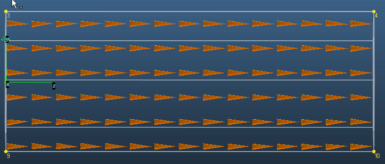
In case of the test pipe, even though the geometry is very simple, there are two “unusual” conditions:
The direction is not at all isotropic, it points towards the strong pump on the outlet (much more molecules go from left to right than back towards the inlet, resulting in a vectorial average pointing right).
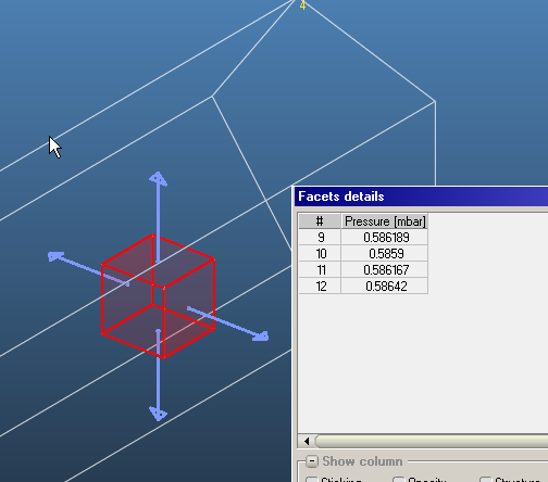
This also means that the pressure in the test pipe is direction-dependent, with a six-walled cube one can show the difference. The four sides have the same pressure:
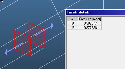
Whereas the front and back have different pressures, of course larger pressure towards the pump:
Finally, it is important that it’s not possible to define exactly how to calculate the pressure on a pump. In reality, the facet represents the entrance of a pump OR a sticking surface (for example a wall with a getter coating).
My choice was that for reflecting walls, the pressure is the contribution of the incident and outgoing impulse change, for desorption, only the outgoing particles contribute, and for pumps, only the incident particles.
Therefore the measured pressure of 0.38mbar on the pump is a combination of two effects:
- Larger than expected pressure due to the directionality of the gas flow, increasing pressures towards the outlet
- Half of the expected pressure for those molecules that stick and not rebound
My argument would be that in non-isotropic (directional) locations, like the test pipe’s area near the pump outlet, it is not possible to measure, or even define the pressure (in simulations or reality), except if you correct for the directionality, for example with the 6-sided cube above. Going a step further, I’d argue that because of this, the textbook formula (Q = p * S) assumes isotropic systems, and is not true when there is strong molecular flow of gas in one direction.
I did a few test cases with pumping speeds of 20, 10, 2, 0.2 and 0.02 l/s, showing the Molflow/textbook pressures:
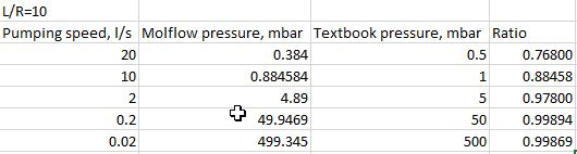
So it seems that the deviation is stronger as we deviate more from the isotropic case.
I’ll discuss with Roberto, the author of Molflow about the issue (which has come up earlier), as my explanation is not complete, and will get back to you.