I have some problems with SynRad code for simulating undulator radiation.
I have simulated radiation from insertion devices, undulator, I put sine/cosine type magnetic field in region
I define a periodic magnetic field, with the format : “period dirX dirY dirZ 1 // A1 B1”
For linear polarization, we must set A1 or B1 zero and then run the code, sometimes, I have seen in region info, the end point is not my defined point and there is 2 or 4 point in “number of point” part.
For example my defined starting point was -114cm and end point was 114cm, but in region info part, I see -114 and -113.8 as start and end point. I fond that with changing MAG file the problem could be fixed(changing from sine cosine in mag file, I mean set B1 zero beside A1 zero). But there is another problem. Each time, I have to make new region and saved param ang MAG files could not be used again.
For circular polarization, I need two magnetic field components, one sine and another cosine. I tried to set two components in 1 region and the result was not correct
Please help me to simulate these type of radiations
Hello Saeid, and thanks for contributing to this forum.
In order for us to debug the code, if it is a bug that causes your problems, please send the syn7z file to us, so we can actually use exactly the same files and geometry. Also, if you have a description, document or text in an e-mail, of the device you want to simulate (the undulator) then that would be nice to have too.
Thanks in advance, and good luck with your study/design.
Hello
I want to explain problems step by step.
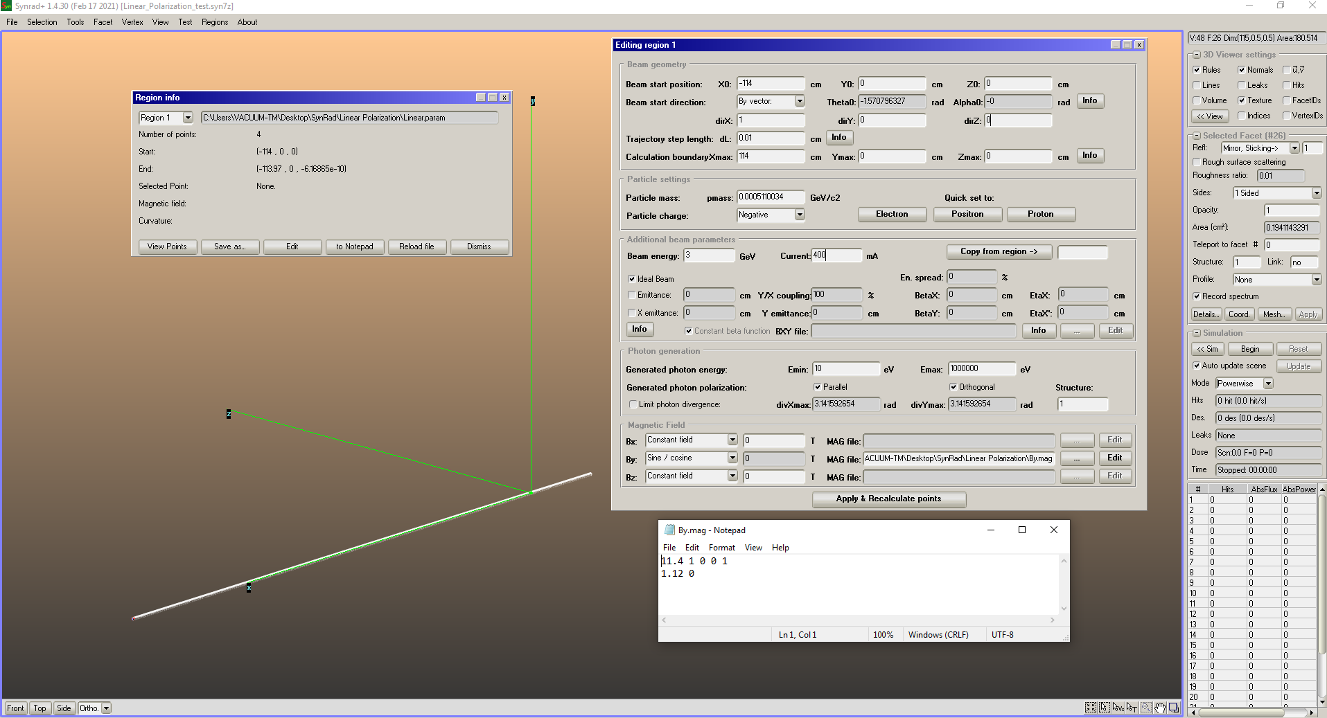
At first, most of the time I deal with this issue in linear polarization: I have defined a region with starting point (-114, 0, 0) and ending point (114, 0, 0), on region info there are (-114, 0, 0) and (-113.97, 0, xxx) as start and end points, as seen in picture.
It happens because you hit the Ymax and Zmax limit at every period (you start the calculation at Y=Z=0, i.e. on the boundary): regions are calculated until either component of the limits is reached.
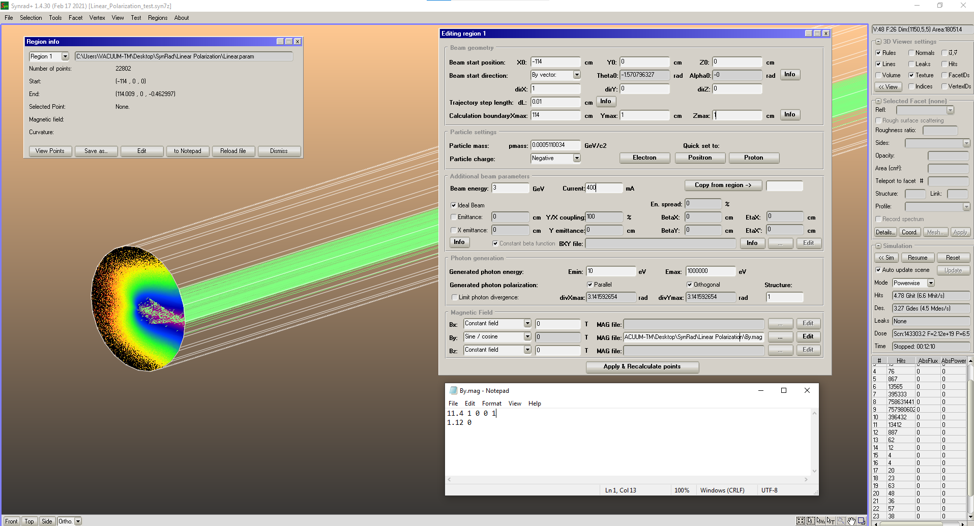
Set Ymax and Zmax to non-zero (for example 999) and it will work.
In both cases, the starting direction has to be fine-tuned so that the ceterline of your wiggler/undulator is on the X axis.
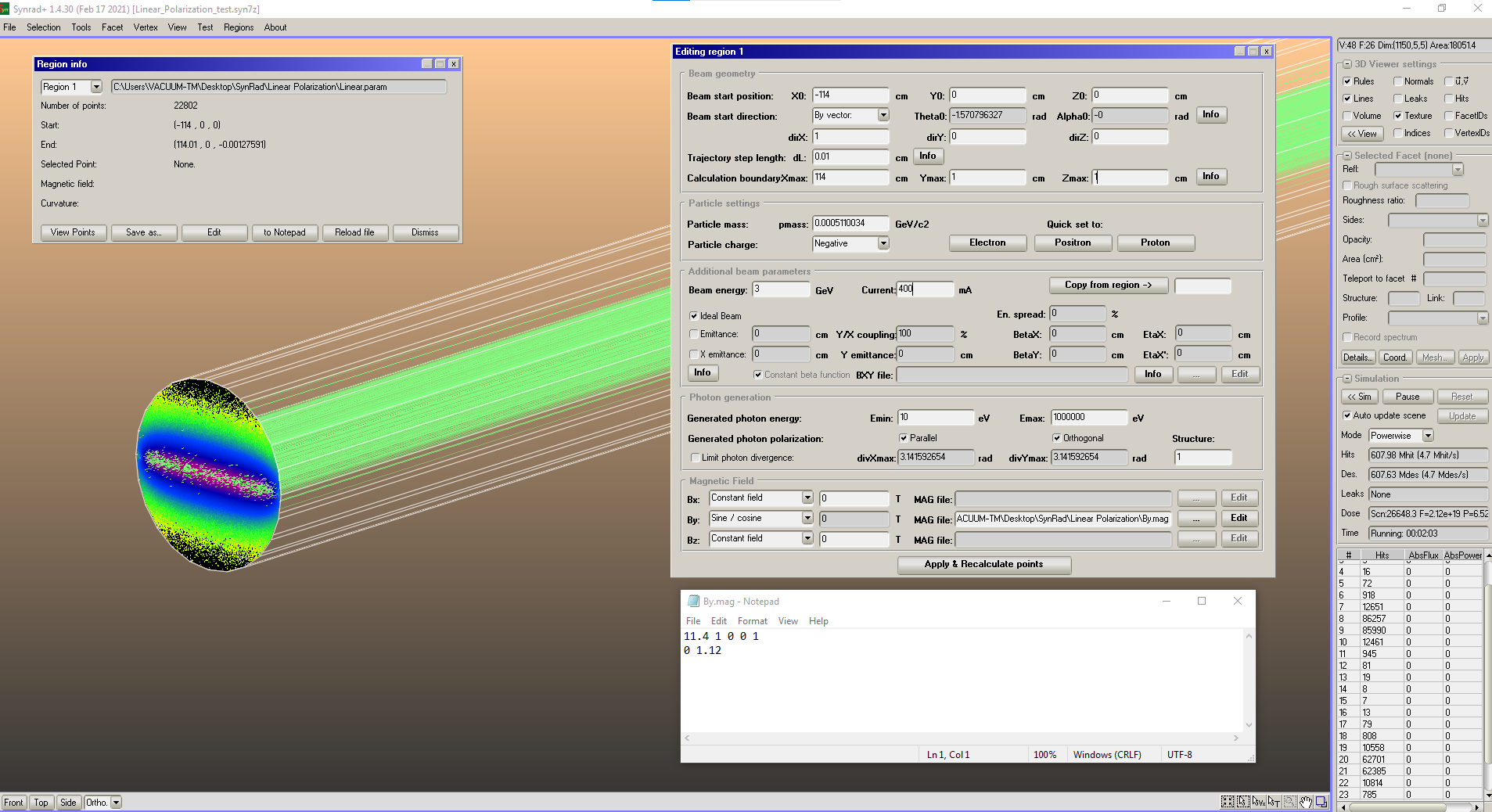
You can check the Z coordinate in the View Points window. It should oscillate within a min/max value all along the X coordinate (length) of the region.
Fine tuning is done through adjusting the theta0 value.