I am working on a sanity-check study that validates Molflow+.
In this work, I want to estimate pressure drop across my system and compare with my experimental data.
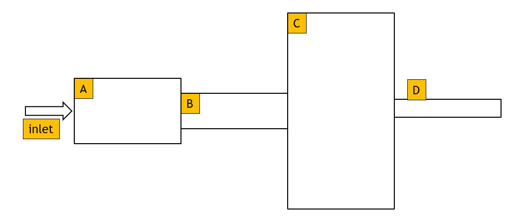
My system is composed of a series of short cylinders with varying radii.
Lets assume the A, B, C & D concentric cylinders have the radii of 4R, 2R, 12R and R and have the same length L.
In my experiment I can set a fixed pressure at my inlet gas, ie, P_in=X mBar, and I measure the flow rate at the outlet , i.e., Y L/s.
At the outlet, I assume that it is at ultra-high vacuum, P_out = 0 mBar.
My first approach is use the throughput equation, delta_P = Q/C where my Q is Y Torr L/s.
I created a geometry of my system in molflow+. In the model,
the sticking coefficient of inlet and outlet are set to 1, and
the outgassing rate is set to 1 mBar L/s at the inlet with a cosine function.
the transmission probability is computed (A_outlet/SUMDES), which is multiplied to the inlet pumping speed to get the conductance of the system, C L/s.
The estimated pressure drop, delta_P = Q/C, is significantly larger than X mBar.
My second approach is to use Molflow+ to estimate the pressure drop directly.
In the model,
the sticking coefficient of inlet and outlet are set to 0 and 0.5, respectively.
the outgassing rate at the inlet as L mBar L /s with the cosine function.
the pressure drop is measure via a texture-enabled transparent cross-sectional
I get the similar answer to that in the first approach, which is larger than X mBar.
Any thoughts on what I have done or assumed incorrectly?
I think the main problem is that close to a strong pump (sticking of 0.5 or 1), pressure becomes a strongly vectorial quantity, so there’s no way to measure it in Molflow -> depending on the measuring facet’s orientation, you will get different results. (Particle density, in contrast, is a scalara quantity, it will always be the same at a point regardless of facet direction).
In method1, you are using Molflow correctly to determine the transmission probability (sticking=1 at both ends), but when you calculate the pressure drop, there is a problem: due to the sticking=1 at the entrance only a fraction of Q will cross the pipe. The equation , similar to an electric circuit, should be:
Q_outlet = delta_P * C
To get Q_outlet, you should multiply P_outlet with the pumping speed of the outlet. The P_outlet is not straightforward to measure because of the directionality mentioned above, but the result should be in the ballpark.
To make a “correct” validation of the Q=C*dP equation, maybe you could try a sticking=0 at the inlet (to make sure that the Q you set at the inlet actually makes it to the outlet), and set a small sticking, like 0.1 at the outlet. This will allow to measure the outlet pressure near the outlet correctly. (One more thing: in Molflow a pumping facet takes into account the pressure contribution of a pumped particle at 1/2 weight, since the particle hits the facet when inbound but isn’t reflected. That’s why at strong sticking factors you can’t measure pressure directly on the pump. But your approach of using a transparent facet is fine)
The second case is closer to my recommended testing, maybe try with a smaller sticking., and measure the inlet pressure with a transparent facet or a profile (instead of directly on the inlet). If the maths is off, please share the geometry thorugh some cloud service and I’ll have a look.
In method1, the measured outlet flowrate (Q_outlet ~ Y mBar L/s) and the estimated conductance (C L/s) were used in the calculation of the pressure delta (delta_P mBar). However, the result is 3x higher than the expected value.
In method2, the model is updated based on your feedback. Specifically,
a sticking coefficient at the inlet and outlet are set to 0 and 0.1, respectively.
two transparent surfaces (opacity = 0) were added to the area of the inlet and outlet (with a small offset away from the respective surfaces).
The pressure delta between these surfaces is similar to the value derived from the first approach, which is 3x higher than the expected value.
I would like to share the molflow model, what is the best method for sharing?
Please share with me the procedure for sharing my model.
Ok, I’ll have a look then!
You can’t upload files in this forum, so I suggest to use any cloud storage (for ex Google Drive as you registered with a Gmail account) and share the link
Looking at your geometry, are you sure the dimensions are right? (All lengths/positions in Molflow are cm)
The largest diameter (entry) facet is a 1.1mm diameter circle, and the length of the full system is 0.4446 mm. Isn’t there a factor of 10 somewhere?
Calculating with the current geometry (in Cern/Molflow preferred units):
The system of interest is a micro-flow channel.
I have verified that the dimensions in the geometry are correct, and the geometry is drawn to scale.
In my experiment, the gas source is connected to the inlet and a bypass.
The bypass is connect to a UPC where i took the inlet pressure reading ~ 30 mBar
The outlet is connected to a vacuum pump, which i assume be pressure reading should be close to 0 mBar.
The system is kept under vacuum sufficiently long such that the outgassing rate of the system is negligible at the beginning of the study.
As the geometry that i created in molflow is a small section near the outlet, i expect that the pressure drop predicted by the model should be less than 30mBar,
Through this study, we found that molflow model predicts a pressure drop of 72mBar. Why do you think we are overestimating the pressure drop?
what physics that we didnt successfully capture in this model?
Molflow assumes molecular flow, which is not the case at 30mbar inlet pressure. Assuming molecular flow is valid up to about 1mbar. (In your case not everything is lost, you can use a textbook formula for choked flow that gives the pressure drop in your pressure regime)
Even in molecular flow, your inlet pressure would be below the pressure drop. The pressure drop is independent of the inlet pressure (as long as in molecular flow regime), but If your inlet pressure is smaller, it can’t be reached as the outlet pressure is already 0.
Thanks Marton for your feedback. The interpretation of the simulation result is clear.
Based on the gas properties and the dimensions of the geometry, the Kn number for this system is ~ 0.05, which i believe to be a slip flow/ rarefied flow regime.
Do you have a recommendation on any off-the-shelf DSMC packages that I can use for this specific task?
You’re right that our thumb rule of “1 mbar” can be relaxed as your system is very small.
I was thinking a bit more about the issue. When applying the Q=C*dP, you can see that the pressure drop is proportional to the gas injection rate (Q). (In fact, in molecular flow every calculated quantity scales linearly with the gas injection, as gas molecules are independent from each other) It means that while Molflow can calculate the conductance with an arbitrary outgassing at the entrance, to get an absolute dP, you need to know the injection rate. This leads to using method 2 (direct simulation of the pressure drop), and unless you know the injection rate from your experimental setup, you have to find the correct value. In your case, you’d have to use a smaller Q (around 0.05 mbar.l/s) and you’d get a matching inlet pressure of ~30mbar and also a correct pressure drop. In conclusion, while you can use Molflow to get the conductance, you need one more fixed variable (either the pressure drop or the injection rate) to apply the Q=C*dP equation.
As for DSMC codes, unfortunately our wisdom stops at the limit of molecular flow, I know that Comsol and Ansys have fluid dynamics modules, but I don’t have personal experience with them.