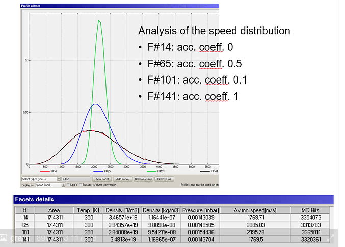
Impact of different accommodation coefficient

Initial task,

  • analyse the impact of the accommodation by varying the temperature for a non-isothermal system
  • useage of the average molecule velocity for analysis

Simplified approach for plausibilisation

  • isothermal system, all faces with the same temperature → expectation that the average molecule velocity inside the system must be the same

I already found this explanation, to be honest I didn’t really understand: Question on Accommodation Coefficient - #3 by maarton

Isothermal system, example on 4 pipes


Questions:

  • Main issue, as input I have 300K on every face, but my output depend on the accommodation coefficient getting different temperatures. I was expecting a temperature of 300K, because there is no additional energy input applied. How is this possible or why is it feasible?

  • Further more, what changes between accommodation coeff. 0 and 0.1?. It looks like there is a step between 0 and 0.1.

  • Calculating the temperature by the ideal gas equation or average mol. speed gives me higher temperatures for a coefficient 0 < coeff. < 1


    Test_Velocity_AccommodationCoeff.zip (17.4 KB)

Version: molflow_win_2.9.25

Hello Thomas.

This is because at non-perfect accomodation, molecules gain speed easier than lose speed. This is what was explained in detail, and with concrete examples, in the discussion you linked.

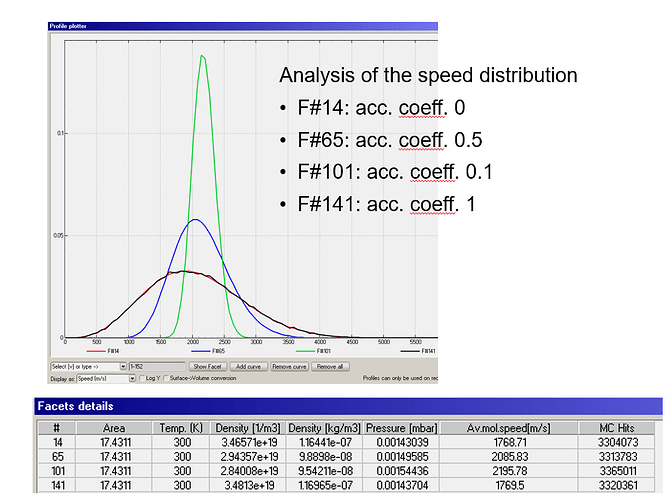
(Please note for the following that you mixed up the annotation of the profiles, F141 is 0 acc. and F14 is 1)

With low accomodation (black profile) and perfect accomodation (red profile), the Maxwell-Boltzmann statistics is followed perfectly, as all particles thermalized perfectly at the last collision (for acc. 1) or desorption (acc. 0).

For in-between, outliers skew the statistics - the equation

image

results in particles gaining speed, due to the mathematical form of the equation.

The rest (higher temp than what the ideal gas equation predicts) is a result of this:

  • The average speed of acc. 0.1 is the highest as they have the most fast particles distorting the statistics
  • The average speed of acc. 0.5 is medium, as fast particles cool down quicker
  • The average speed of acc. 1 and 0.1 is the lowest, as fast particles are thermalized instantly after a hit

Using an accommodation coefficient of 1 → every particle will be fully thermalized by the surface
accommodation coefficient of 0 → no particle will be thermalized

So far so good, that I understand and is plausible to me.

In my system every surface has the same temperature of 300K and therefore an average velocity. By using an accommodation coefficient 0 < coeff. < 1 I get a higher temperature in my system.
Energy input is not equal with my energy output

"By using an accommodation coefficient 0 < coeff. < 1 I get a higher temperature in my system.
Energy input is not equal with my energy output"

I verified and the avg. temperature and avg. energies are the same for all four cases, see attached calc. after exporting speed distributions.

energies.xlsx (26.2 KB)

How did you calculate the temperature and energies?

Yes, the distributions itself are consistent, but as I calculated before:

My input particles have an energy in terms of temperature of 300K, all walls have a temperature of 300K.
How it can be, that my output from all of this have a higher temperure than my input?

For me, there is still a missing link, despite your explanation in statistics before

The problem is that you’re using the ideal gas equation to calculate the temperature, and I assume the energy (although you didn’t reply how you calculate that), whereas only the acc=1 and acc=0 cases are ideal gases.

For non ideal gases, where the speed distribution does not follow the MW distribution, the energy and temperature are calculated by my method (which is valid for ideal or non ideal cases as well), integrating the square of the velocities over the distributions. You will get the same energy and temp. for all four cases.

" The problem is that you’re using the ideal gas equation to calculate the temperature, and I assume the energy (although you didn’t reply how you calculate that), whereas only the acc=1 and acc=0 cases are ideal gases."

I didn’t caluclate it, I see it on the evaluation on the face itself. When the average velocity on a face shift from 1768m/s (acc. 0 or 1) to 2085 or 2195 m/s (0< acc. <1) then I have an energy input somehow.

“For non ideal gases, where the speed distribution does not follow the MW distribution, the energy and temperature are calculated by my method (which is valid for ideal or non ideal cases as well), integrating the square of the velocities over the distributions. You will get the same energy and temp. for all four cases.”

Why isn’t it an ideal gas anymore?
When you calculate the distributions the energy is the same, I am questioning those distributions.

Nevertheless I made some basic example in Excel. Which describes my understanding and expacted outcome, based on the test case above.

Molflow_Plausibilisation_20241009.xlsx (4.2 MB)

“I didn’t caluclate it, I see it on the evaluation on the face itself.”

That’s the facet (wall) temperature, the one that you set, not the measured gas temperature on that facet. I can rename it in future versions to be more clear.

“When the average velocity on a face shift from 1768m/s (acc. 0 or 1) to 2085 or 2195 m/s (0< acc. <1) then I have an energy input somehow.”

Thomas, I still don’t understand why you say that you have energy input. I have shown you and attached my calculations that you don’t have energy input. The energy is exactly the same in all four cases, despite the different average velocities.

“Why isn’t it an ideal gas anymore?”

Because the velocity distribution isn’t Maxwell-Boltzmann.

I’ll have a look at your Excel sheet in detail.

Regards, Marton

If you allow a few questions on your Excel:

  • You go from RMS to average speed as follows: v_avg = v_rms / 1.085

Why?

I have corrected your Excel sheet:

  • I made a copy of the surface sheet
  • I calculate the new wall speed, not its square (energy)
  • Instead of your division of RMS by 1.085 which assumes ideal gas, I calculate the real average
  • You can see the speed increase for cases between 0 and 1:

Molflow_Plausibilisation_20241009_marton.xlsx (5.7 MB)

“That’s the facet (wall) temperature, the one that you set, not the measured gas temperature on that facet. I can rename it in future versions to be more clear.”

I don’t mean the “Temperature”, the average molar velocity is higher as I said (therefore you can calculate a temperature).


When I see this my particles have an higher Energy than my Input.

“The energy is exactly the same in all four cases, despite the different average velocities.”
If you look only on the distribution itself. If you look on the system, my particles start with an average of 1780 m/s and end with 2200 m/s.

“You go from RMS to average speed as follows: v_avg = v_rms / 1.085”
Transition from v_rms to v_avg

“I calculate the new wall speed, not its square (energy)”
According to the link before, for energy balance v_rms is used:
grafik

Thomas, please slow down and read what I write. You’re repeating the questions I have already answered.

“I don’t mean the “Temperature”, the average molar velocity is higher as I said (therefore you can calculate a temperature).”

I already wrote that you can’t use the ideal gas equation to convert it to temperature, since the acc=0.1 and acc=0.5 cases aren’t ideal. The temperature is related to the energy of the system.

“If you look only on the distribution itself. If you look on the system, my particles start with an average of 1780 m/s and end with 2200 m/s.”

Yes, we both agree that the velocity increases, but the energy is the same! Again, velocity can’t be converted to energy or temperature for non-ideal gases.

“When I see this my particles have an higher Energy than my Input.”

No, you don’t. In the Excel sheet I corrected, you can perfectly see that the energy is the same but the average velocity isn’t. It proves that average velocity can’t be converted to energy, except for ideal gases. Look in detail:

Your v_rms is the same (same energy):

But your v_avg differs (different avg velocity):

“Transition from v_rms to v_avg”

The link assumes Maxwell-Boltzmann, it isn’t valid in the acc=0.1 to acc=0.9 cases where the gas doesn’t follow the MW. You can’t divide v_rms by 1.085 but you have to actually average the velocities, which I do in the new Excel sheet.

“According to the link before, for energy balance v_rms is used:”
grafik

Yes, but I’m not interested in the energy, but the speed, to prove you that the average velocity increases and the energy doesn’t! Your Excel sheet calculated the energy, then wrongly deducted the average speed by dividing with 1.085, which is incorrect for non ideal gases.

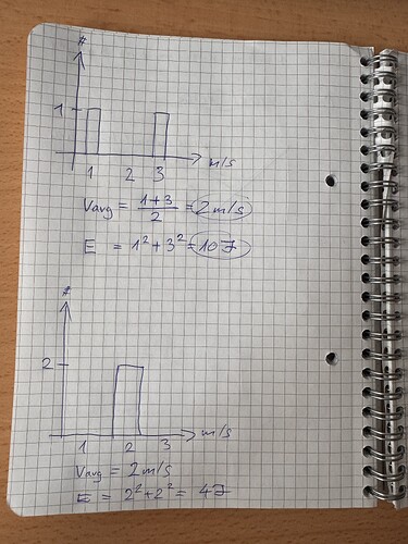
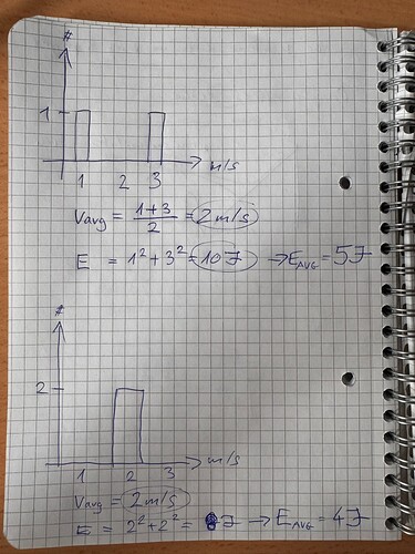
In this example I show why you can’t convert speed to energy or temperature.

Both distributions have 2m/s average velocities but very different temperatures and energies.

“Thomas, please slow down and read what I write. You’re repeating the questions I have already answered.”
I am really doing it :sweat_smile:

I look at the system and the result I can get on the facets and lets say I don’t care what is happening inside. For me it looks like this (I wrote it in v_avg to better compere it with values before, v_rms should be used):

Let’s say v_avg should be used, and this is now correct?

Here I don’t have this strong increase of the velocities from accomodation coeff. 0 to 1 and also the step between 0.1 to 0, like here:
grafik

“Here I don’t have this strong increase of the velocities from accomodation coeff. 0 to 1 and also the step between 0.1 to 0, like here:”

Because your Excel sheet is simulating a single wall reflection. It increases velocities slightly, but repeated collisions with the wall (as in MolFlow) exacerbate that effect. You could modify the Excel sheet with additional columns to simulate further collisions and verify.

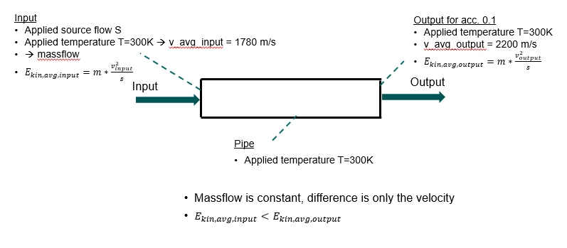
The image is wrong. You use the formula E_kin_avg = m* v^2/s

image

The mistake is that you’re squaring the average, not averaging the square.

The correct formula is:

E_kin_avg = m* sum(v^2) / s

(you don’t annotate s, I assumed it is the number of molecules)

This is what I demonstrate in the hand-drawn sheet of paper (I fixed a small typo):

Both distributions have 2m/s average velocity, but one has average energy of 5J, and the other 4J.

If you take one thing from this discussion, it should be that the average velocity of the gas does not tell anything about its temperature or its energy, except the special case of ideal gases, which are all over the textbooks as the most typical case, but not in non-isothermal systems. Bad news is that if you’re in plasma physics, you’ll deal most of the time with non-ideal gases :slight_smile:

“Because your Excel sheet is simulating a single wall reflection. It increases velocities slightly, but repeated collisions with the wall (as in MolFlow) exacerbate that effect. You could modify the Excel sheet with additional columns to simulate further collisions and verify.”

As I suggested v_rms should be used in my opinion. Further more, that doesn’t explain the step from acc. of 0.1 to 0 → there should be at least some kind of transition.

“The image is wrong. You use the formula E_kin_avg = m* v^2/s”
Yes it should be E_kin_avg = m* v_rms^2/2

ok then we don’t align, my understanding of energy is this:

"If you take one thing from this discussion, it should be that the average velocity of the gas does not tell anything about its temperature or its energy, except the special case of ideal gases, which are all over the textbooks as the most typical case, but not in non-isothermal systems. Bad news is that if you’re in plasma physics, you’ll deal most of the time with non-ideal gases "

In this example I don’t have a plasma, and also I don’t have a non-isothermal system.

Sry, I don’t see why an interaction with a wall changes the characteristics from an ideal to a non-ideal gas.

We both agree.

So far you have used “avg” i.e. average speed, which is different from the RMS speed.

From your posts above:

image
image

These are average, not RMS speeds.

Molflow shows the average speed, not the RMS speed. The RMS speed (not displayed by MolFlow, but shown in my first Excel sheet) is the same for all four cases.

" that doesn’t explain the step from acc. of 0.1 to 0"

Why do you not do the debugging yourself? You can see molecule by molecule what happens with your Excel sheet, and find the root cause why a 0.1 accomodation factor causes a deviation from the perfect MB case (acc=0).

“also I don’t have a non-isothermal system”

Sorry for the different nomenclature, your walls in this case are indeed isothermal.

“Sry, I don’t see why an interaction with a wall changes the characteristics from an ideal to a non-ideal gas.”

You just proved with your own Excel sheet that the velocity distribution changes with the accomodation coefficient:

This means that the distribution isn’t MB anymore, thus the gas isn’t ideal.

As for your private message, we give Molflow to the community for free, and in this case I’ve spent over an hour helping, but we don’t have resources for video calls to users.

grafik

I wanted to show you the numbers from input and output, that they are different, vms speed correlates to it. Also I said, v_rms should be used.

" Molflow shows the average speed, not the RMS speed. The RMS speed (not displayed by MolFlow, but shown in my first Excel sheet) is the same for all four cases."
I also know that.

“Why do you not do the debugging yourself? You can see molecule by molecule what happens with your Excel sheet, and find the root cause why a 0.1 accomodation factor causes a deviation from the perfect MB case (acc=0).”

Therefore we don’t agree using the average speed.
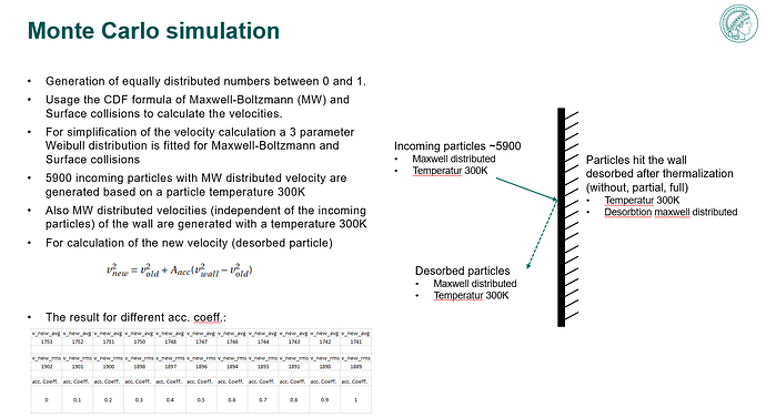
You express the accommodation coefficient in terms of energy (Question on Accommodation Coefficient - #3 by maarton):

"New_energy = old_energy+(wall_energy-old_energy)*accomodation_coefficient

in simple terms, acc=1 will alwas assign “wall energy” (Maxwell-Boltzmann distribution according to wall temperature), acc=0 will keep old molecule speed, and acc=0.5 will take the average energy between old and wall."

“You just proved with your own Excel sheet that the velocity distribution changes with the accomodation coefficient:”

I proved my argument, you modified it to prove yours.
So we can agree that this excel example represents the principle?.

And I think the main disagreement is, which speed should be used?

One argument you have, it isn’t an ideal gas, is there some literature where this effect is explained?

“As for your private message, we give Molflow to the community for free, and in this case I’ve spent over an hour helping, but we don’t have resources for video calls to users”
It is ok, just thought it would be easier and time-saving. And for me around two days :slight_smile:

Dear Thomas,

I’ve spent a lot of time to investigate this issue to make sure that MolFlow doesn’t do something wrong (which has indeed happened before in the past and thus we fixed it).

I’ve written on at least four occasions that the average speed does not tell anything about the temperature or energy of the gas. I went as far as drawing distributions to demonstrate that you can keep the average speed constant yet have different RMS speed, temperature and energy. Yet you repeat “I wanted to show you the numbers from input and output, that they are different, vms speed correlates to it.” No, it does not correlate.

I don’t see anything that suggests that MolFlow is unphysical or numerically incorrect. All the “problems” you found, such as “input of energy”, are due to what we believe are mistakes, such as calculating the energy/temperature from the mean speed, or getting the mean speed by dividing by 1.085, or using the ideal gas equation for non-ideal gases.

To use the ideal gas equation (or assume MB distribution), perfect thermal equilibrium is assumed. In molecular flow there are no intermolecular collisions, so only the wall thermalizes. When you deviate from perfect (acc=1) wall thermalization, you take away this last thermalization source, and the equilibrium is broken, thus the gas is not ideal. To me it is obvious, but if you really want literature, here is a paper where they test gas properties at different accomodation factors: Gas flow towards an adsorbing planar wall subject to partial gas-surface thermal accommodation - ScienceDirect

I suggest to end this discussion here. You reported a bug, and we don’t believe it is an actual bug.

Regards, Marton

Dear Marton,

to sum it up. I talk to some other physisits in my department and go through the argumentations in this discussion to get other opinions. They see no physical explanation why the output of the example as isothermal system with ideal gas inside differ for different accommodation coefficients.
I also send you links why I did certain things and where they are coming from (e.g. “the mean speed by dividing by 1.085”).

Yes, we can end this discussion here.
I would be happy to discuss it on a call with you or someone else, who support your argumentation.

Best regards,
Thomas